As part of the development of the DBG high tuck mirror stems (LINK), I was fortunate to have a a few Z3M mirrors of both variants in my hands. As such, I had the opportunity to learn some during my disassembly/reassembly of both the manual and auto dim cabin rear view mirrors. This DIY is geared towards the installation of a DBG mirror stem but can be used for auto dim glass replacements or manual dim tilt knob replacements as well.
Due to aging plastics and mirror assembly methods, it is HIGHLY recommended to disassemble all mirrors to install the DBG stem to avoid breaking the casing/glass of the mirrors.
Tooling/Materials:
- Small plastic trim removal/pry tool(s)
- Straight/90° pick
- Small flat blade screwdriver
- Isopropanol Alcohol
- 21mm(+/- 1) socket or similar size cylinder to support stem installation
Manual Dim variant:
- DBG tilt knob (Optional) LINK
Auto Dim variant:
- Medium Ziptie (autodim mirror stem V2 replacement only)
- Tape (I use 3M Super 33+)
- Superglue/adhesive of choice (glue & accelerator)
- 220 grit sandpaper
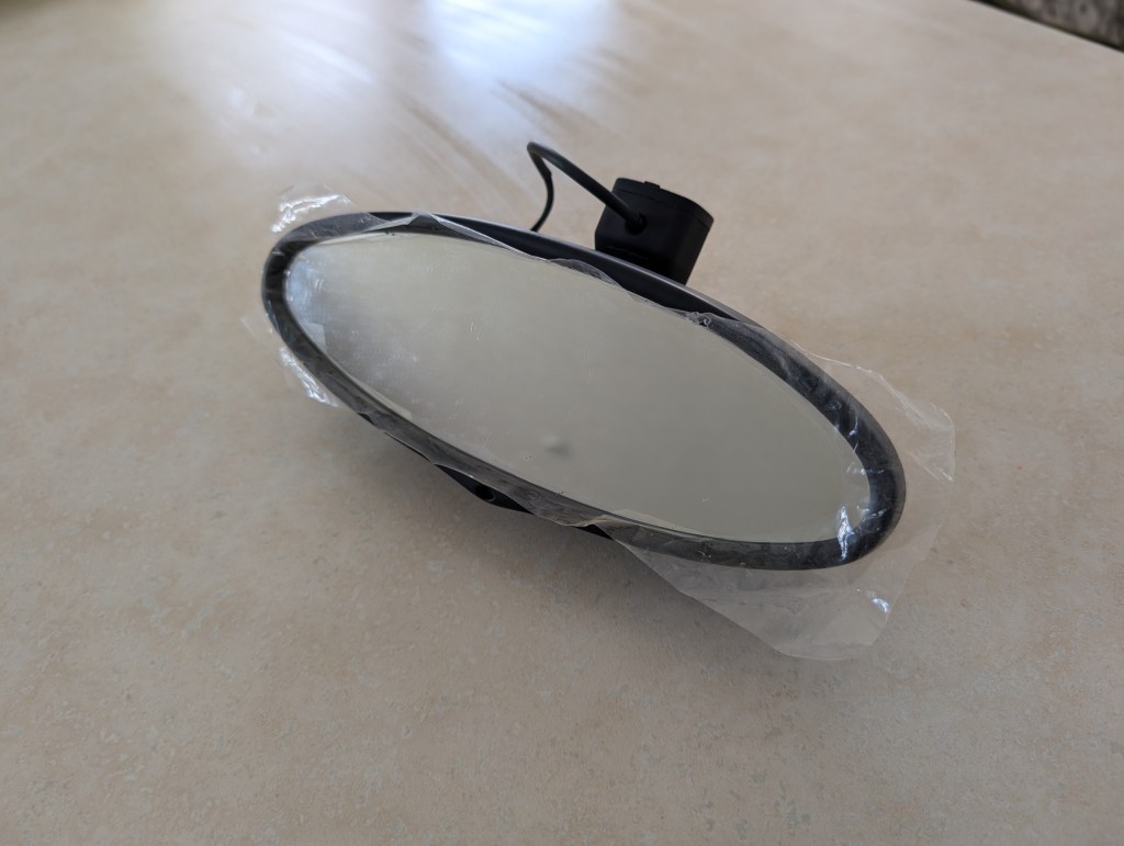
BMW mounts their rearview mirrors with a spring clip twist attachment to remove either mirror from the windshield, position the mirror down, and rotate (either direction) approximately 120° (1/3 of a full rotation) to release the spring clip. For auto dim variants, the plug for the wiring must be disconnected prior to removal and is located in the mirror stem that is accessed from removal of the aft facing cover on the OEM stem.
Once the mirror is removed from the car I work on a towel folded over on a coffee table, I mean workbench, for disassembly.
We will start with the manual dim variant process. For auto dim applications, scroll down to the section for auto dim.
Manual Dim Mirror
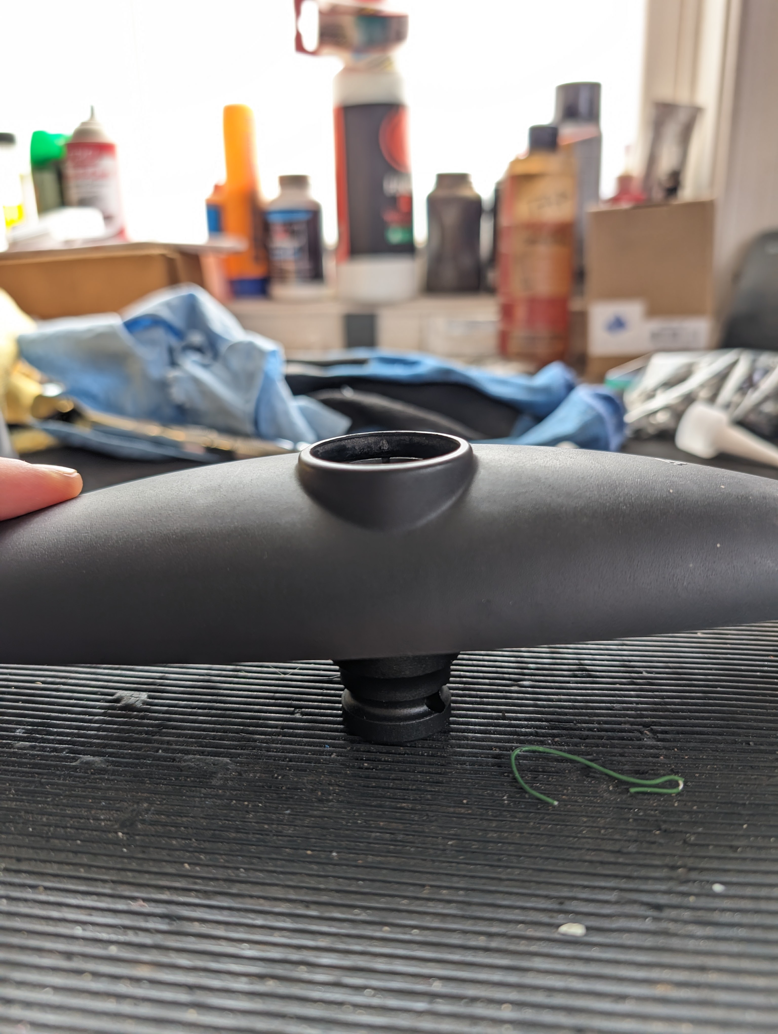
- position with glass down and socket assembly accessible. The socket assembly tension is held with a spring clip and will need to be removed.
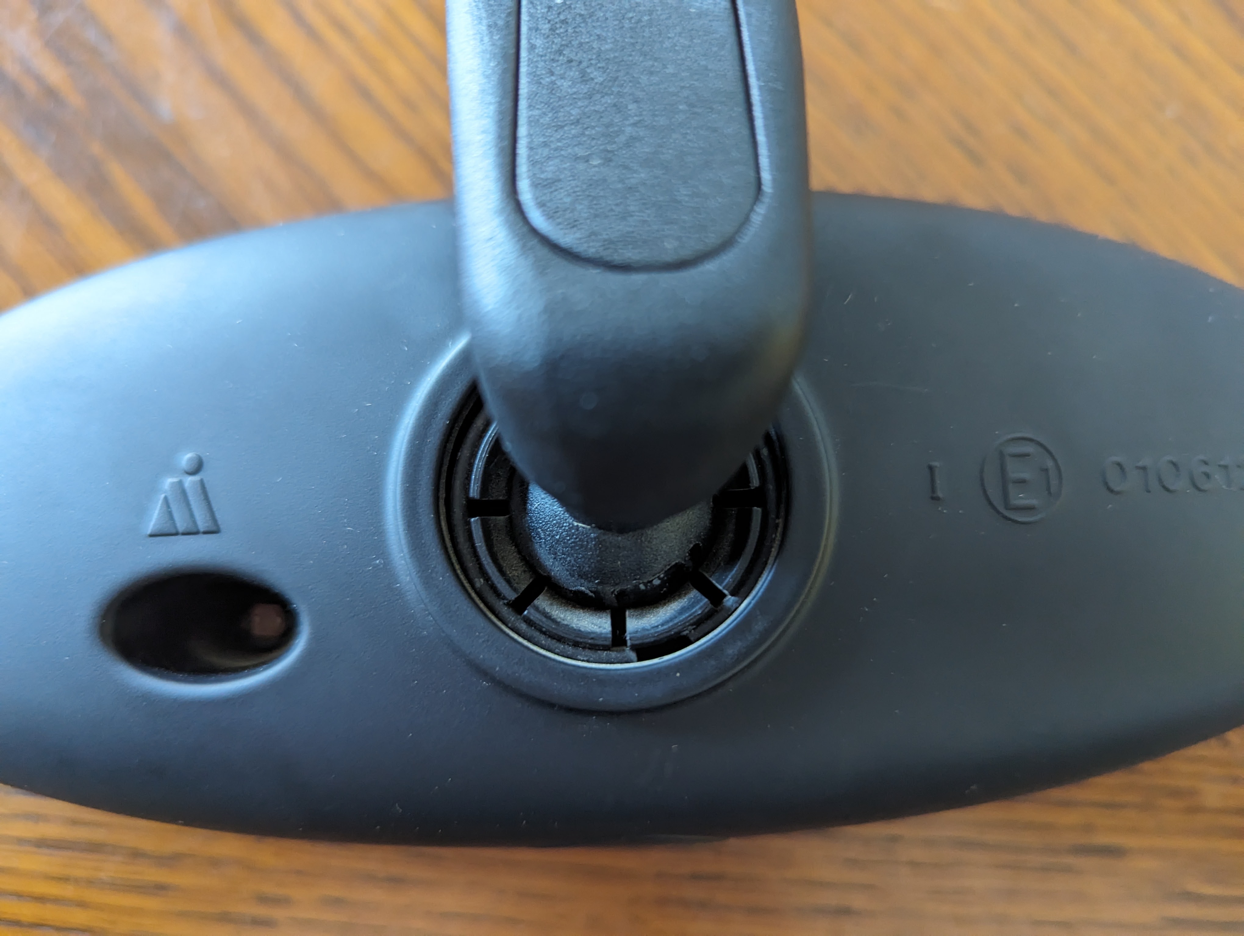
- Locate the spring clip joint and using a pick pull the ends up and work the clip out of the joint. (Note: photos shown are the auto dim but the socket is disassembled in the same manner)
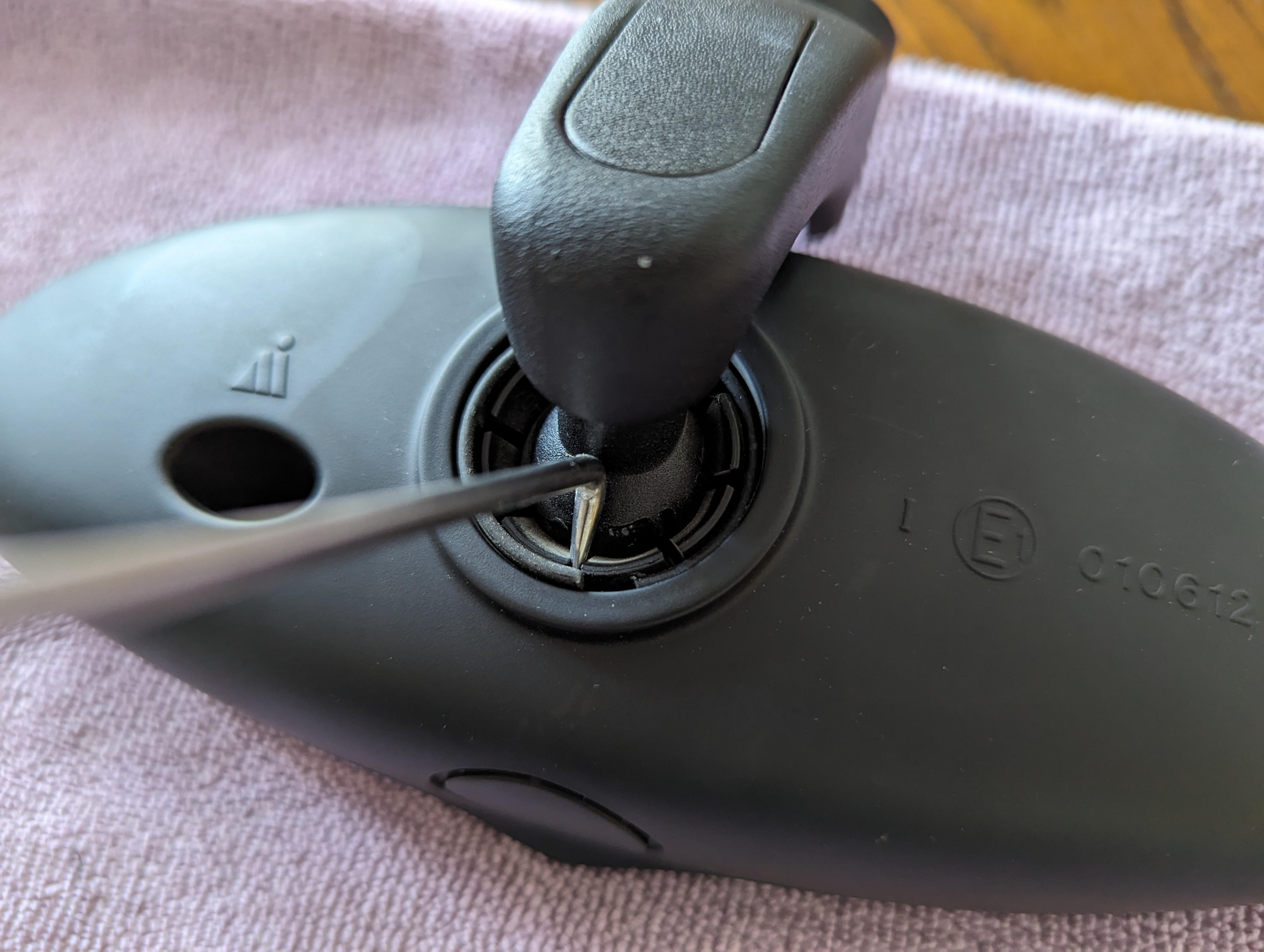
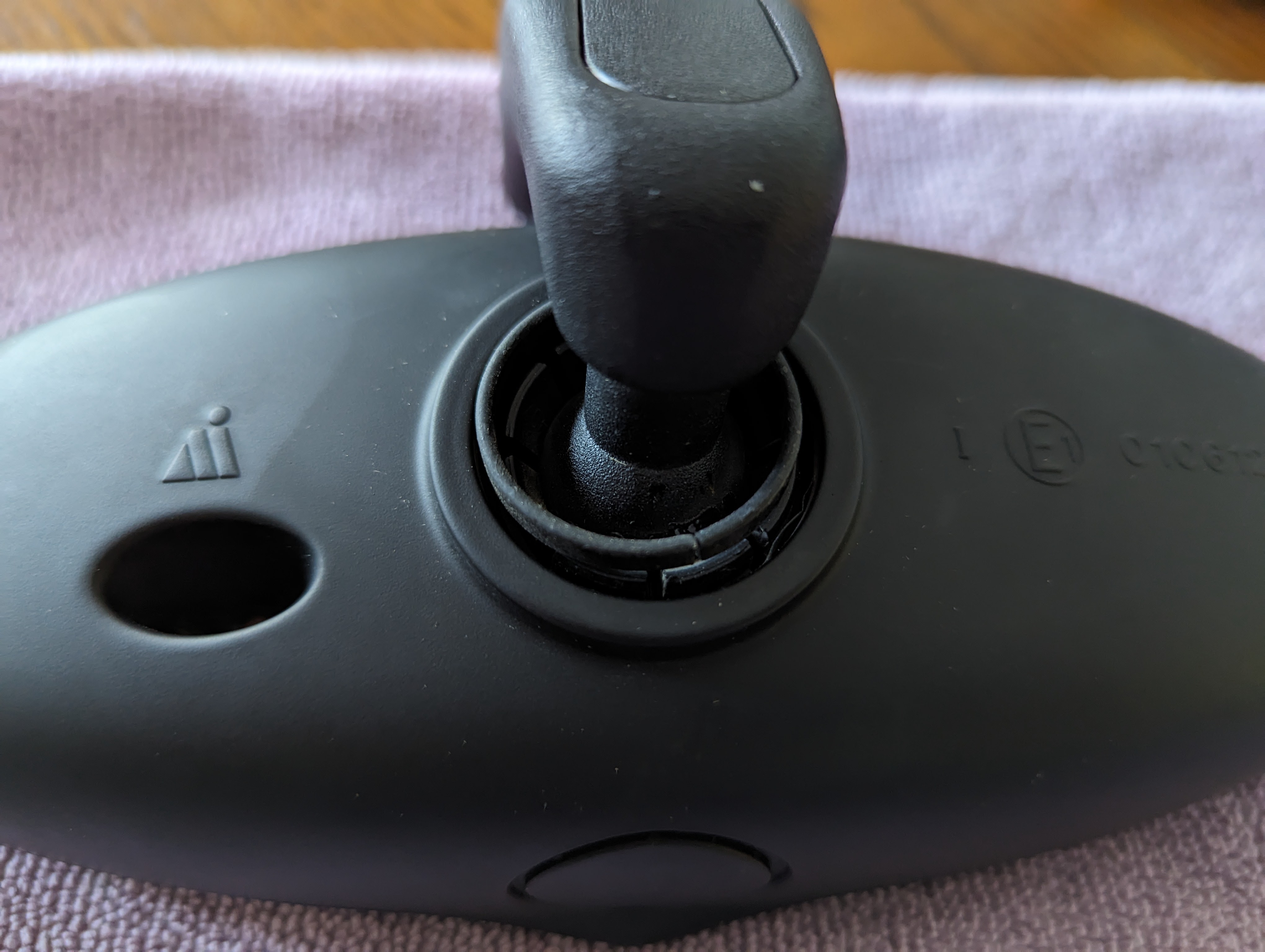
- With the spring clip out of position, apply a small amount of alcohol to the ball for added lubrication for disassembly and rotate the ball from the socket joint.

- From the removed stem, remove the 3 each M3 screws and retain the mounting plate, screws, and 3 each spring rods to affix to the DBG stem*
*Note: V1 stems will make right up tight. Due to an error during V2 development the counterbores were undersized and required the removal of the mounting plate bosses by sanding them flush with the plate. Leaving these bosses in place could cause looseness of the spring rods when affixed in place.
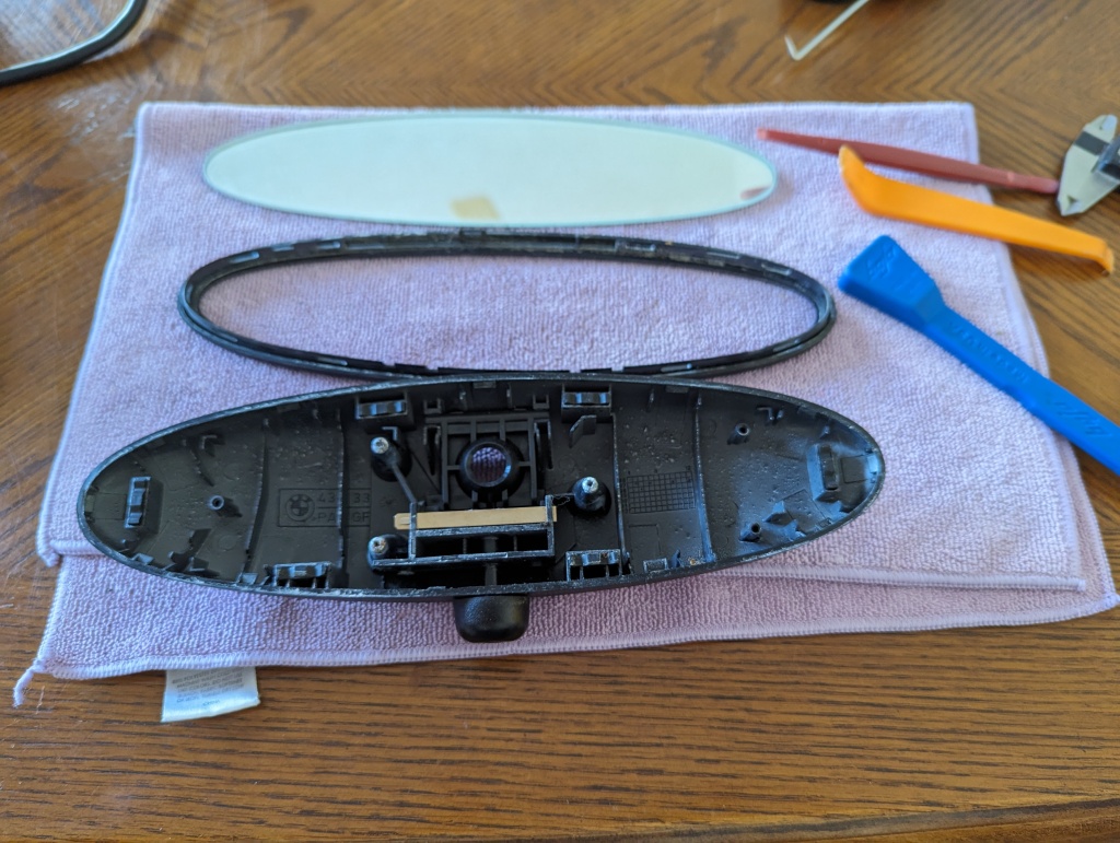
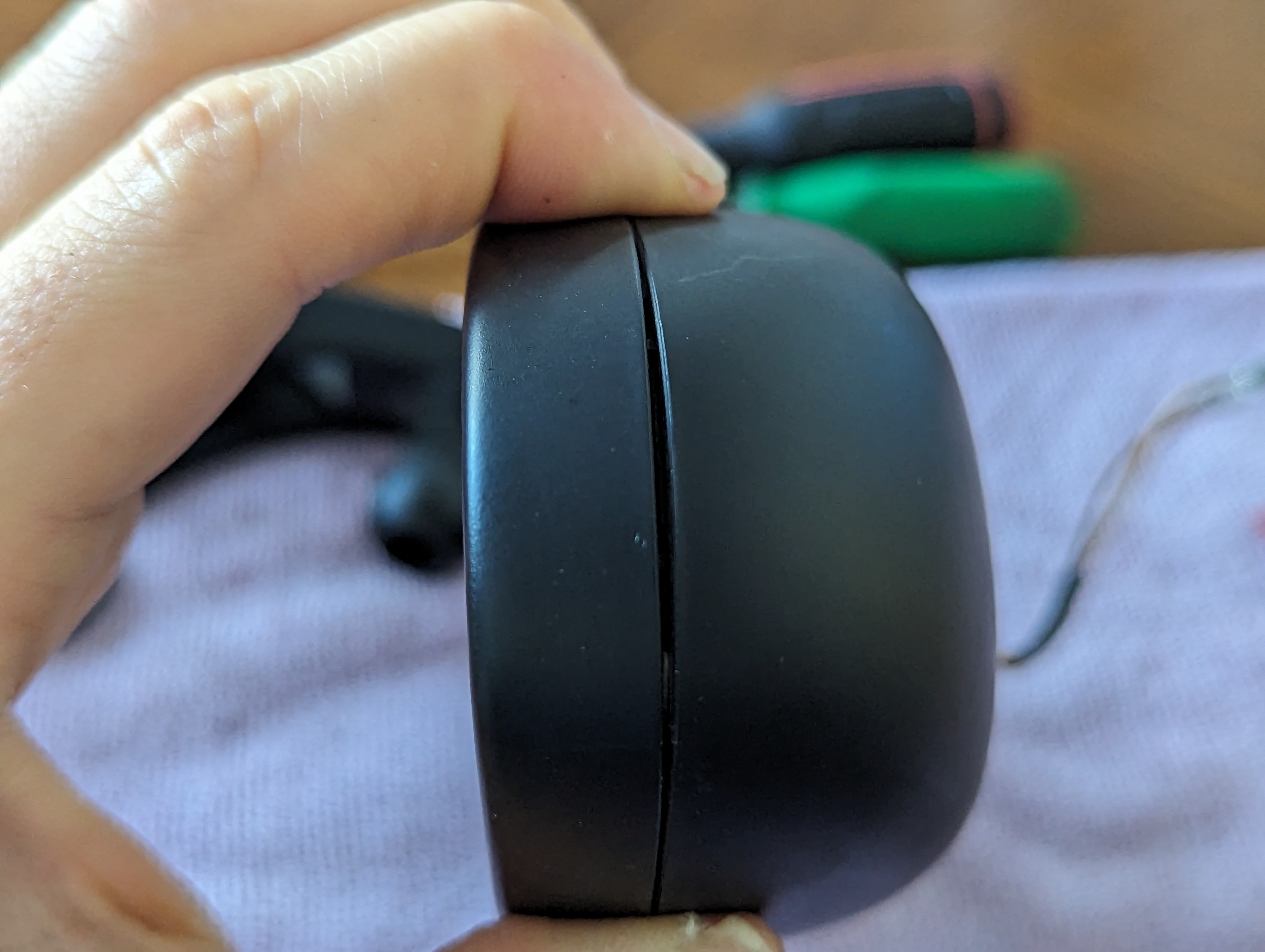
- The casing of the manual dib mirror has the tabs on the mirror ring and the hooks in the rear casing. Using the pry tools, separate the mirror ring from the rear casing as shown
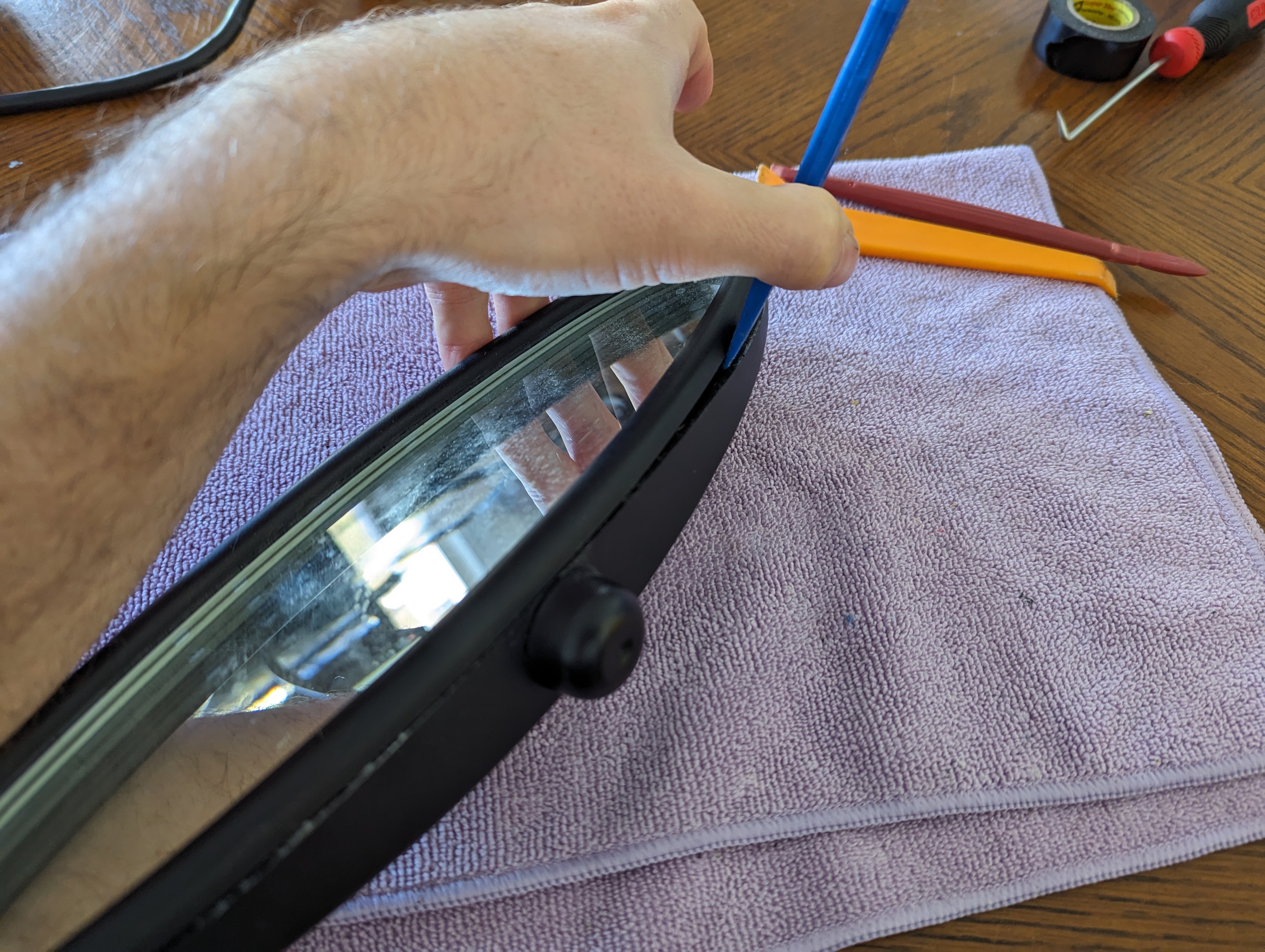
- With the mirror ring completely loose, the mirror should come apart in three pieces, the mirror ring, the mirror glass, and the rear casing.

Note: If solely replacing the mirror stem, skip to step 10. The following will detail the replacement of the manual dimmer knob/ adjustment cam.
- Depress the spring bar barb and slide the spring bar out of position and remove.

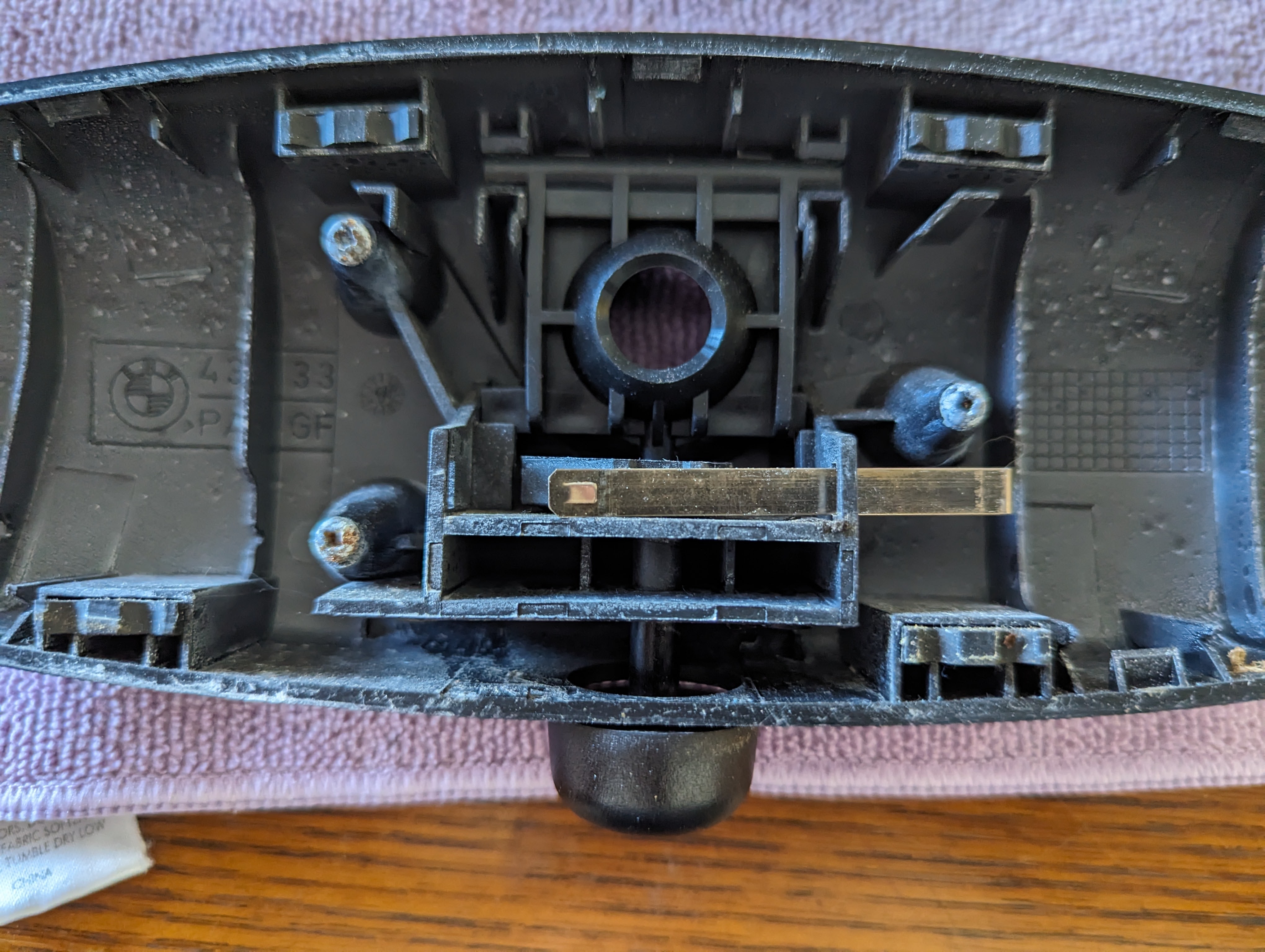
- To replace the adjustment cam to stem socket needs to be removed. Carefully pry the pivot points out of their position, take note that there are two tabs at the bottom that can be broken off if too much force is applied (whoops).
- With the socket removed the cam should lift out of the rear case, if present the adjustment knob will pull down off the stem with light force.
Note: The DBG adjustment knob/cam is a SINGLE installation use part. Once installed they will not likely come back apart without destructive results.
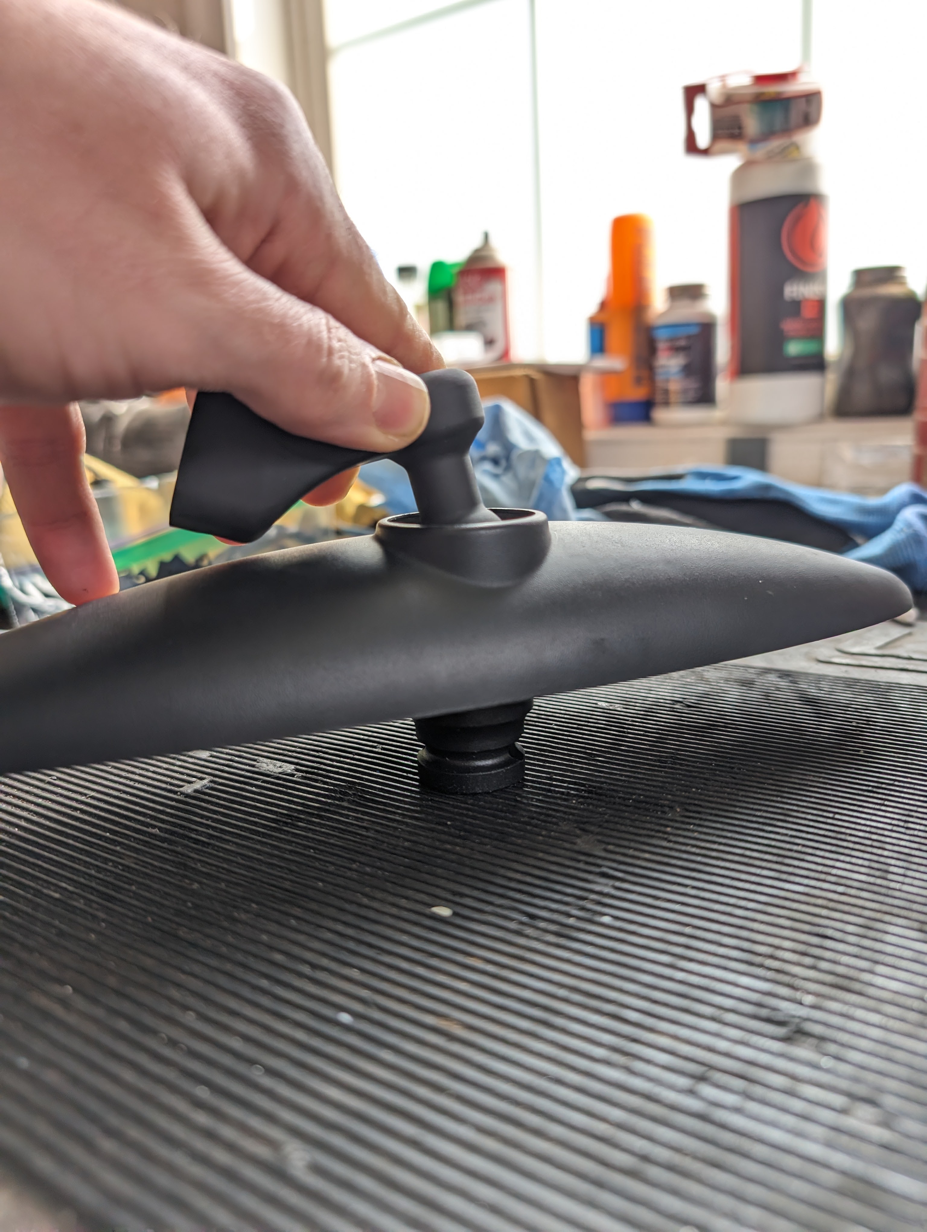
- Prior to reassembling the mirror ring, glass, and rear case install the DBG mirror stem into the socket in the rear case. During installation, ensure the tool socket (or other material) is supporting the mirror ball socket to ensure pressure from the stem installation is directly translated to your workbench and not through the socket support structure/rear case.
- Reassemble in the reverse operation with the DBG parts as applicable.
Auto Dim Mirror
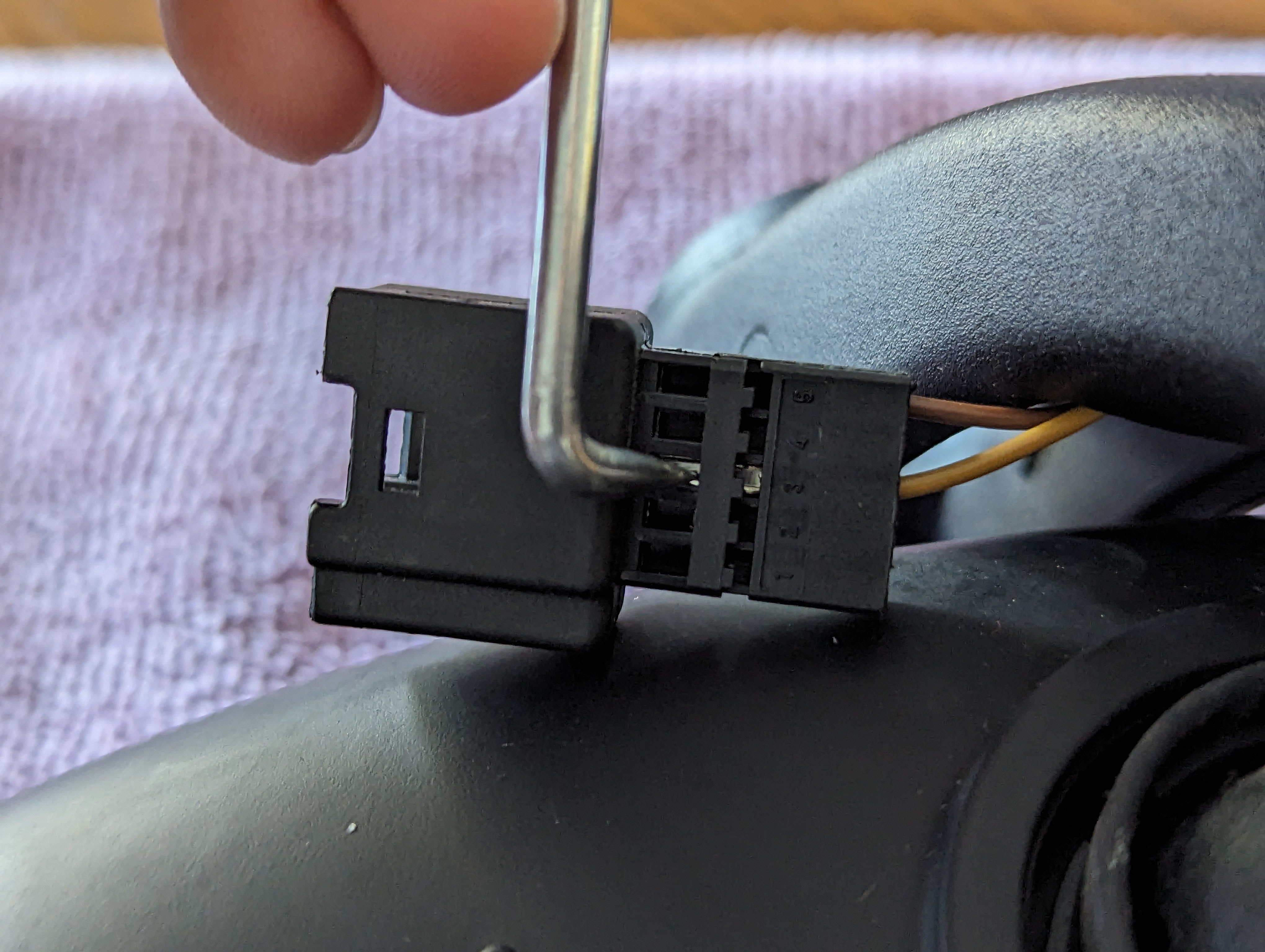
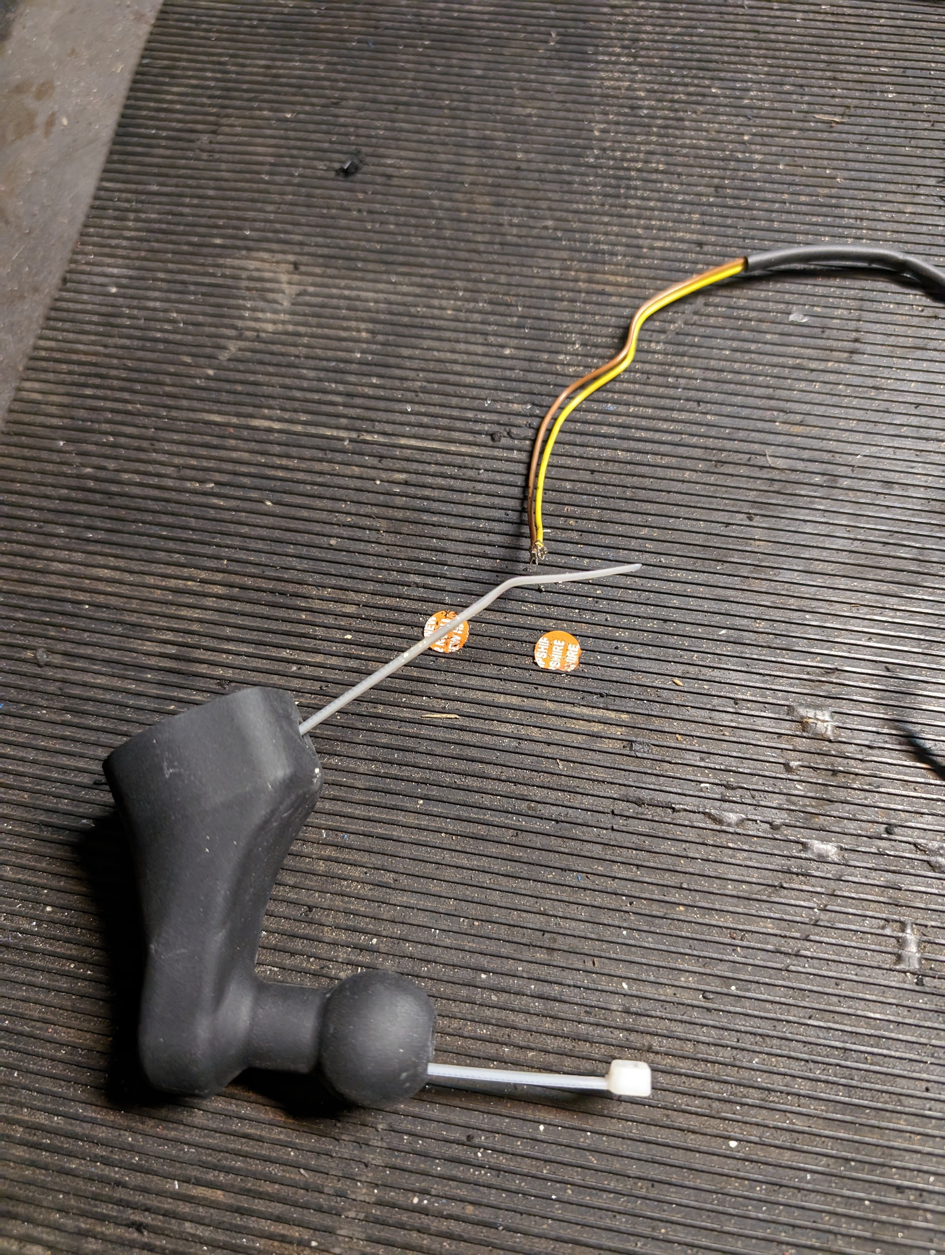
- To remove the wiring harness from the existing stem, disassembly of the chassis side plug is required. Begin by sliding the disassembling the plug housing from the plug by sliding back the closure cover and sliding off the locking cover.
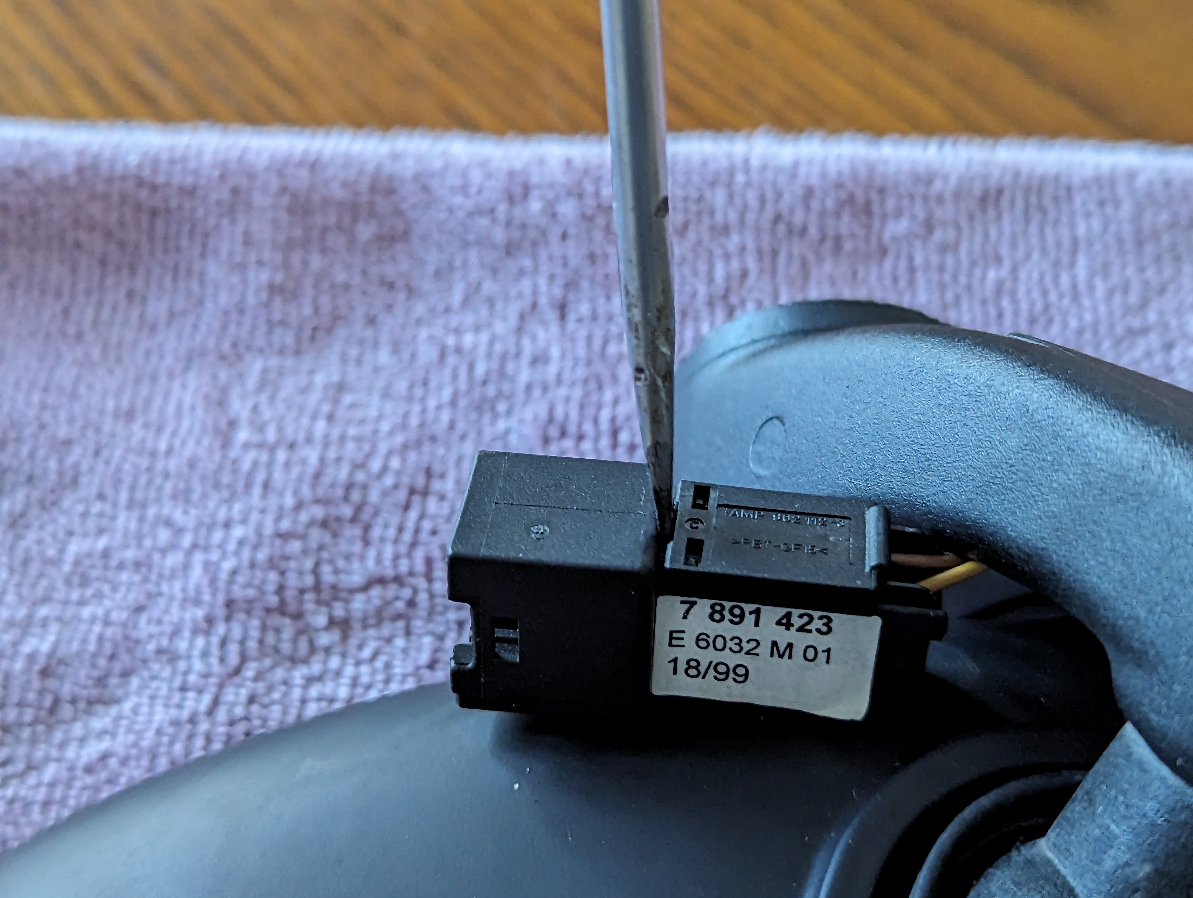
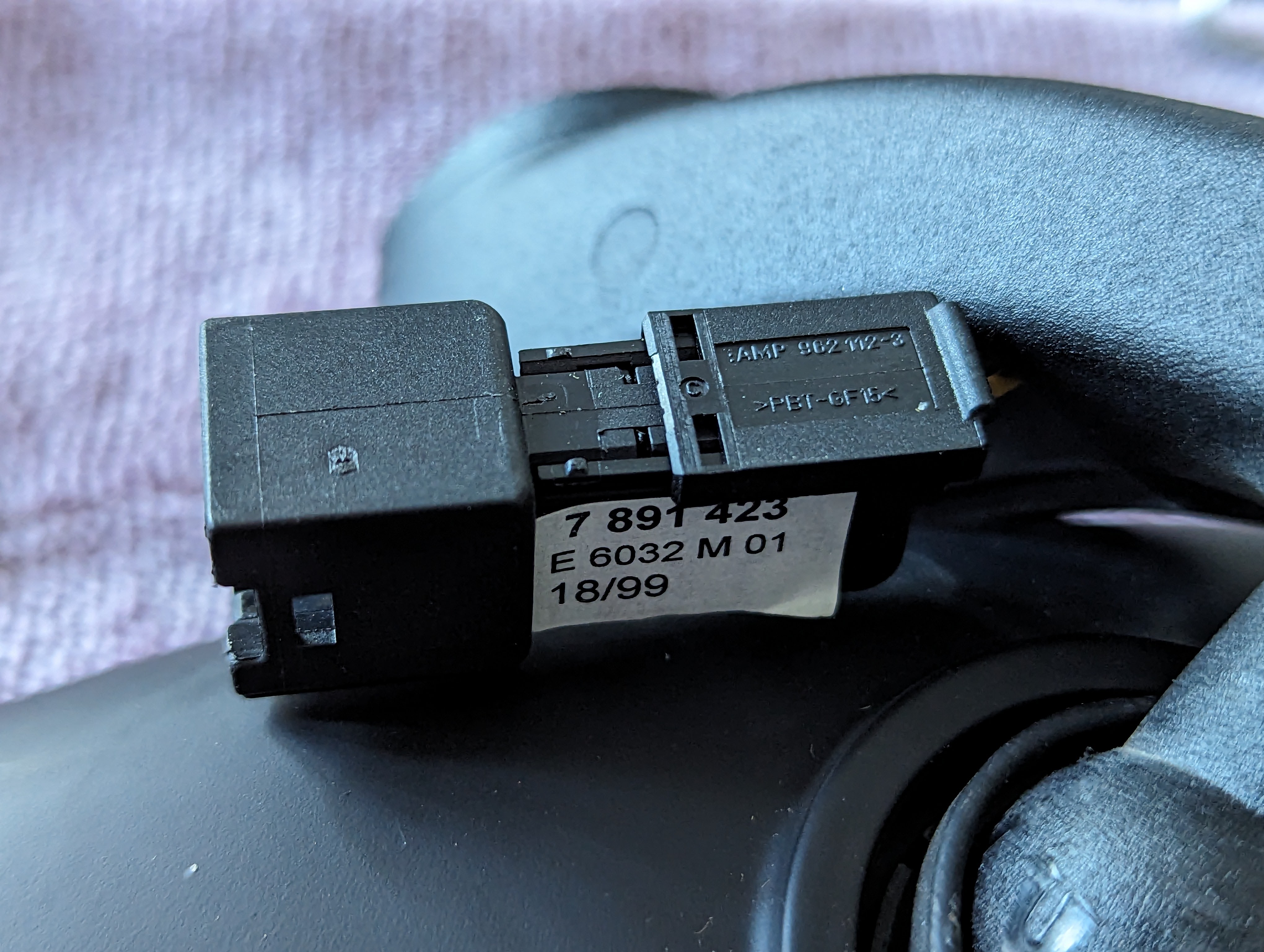
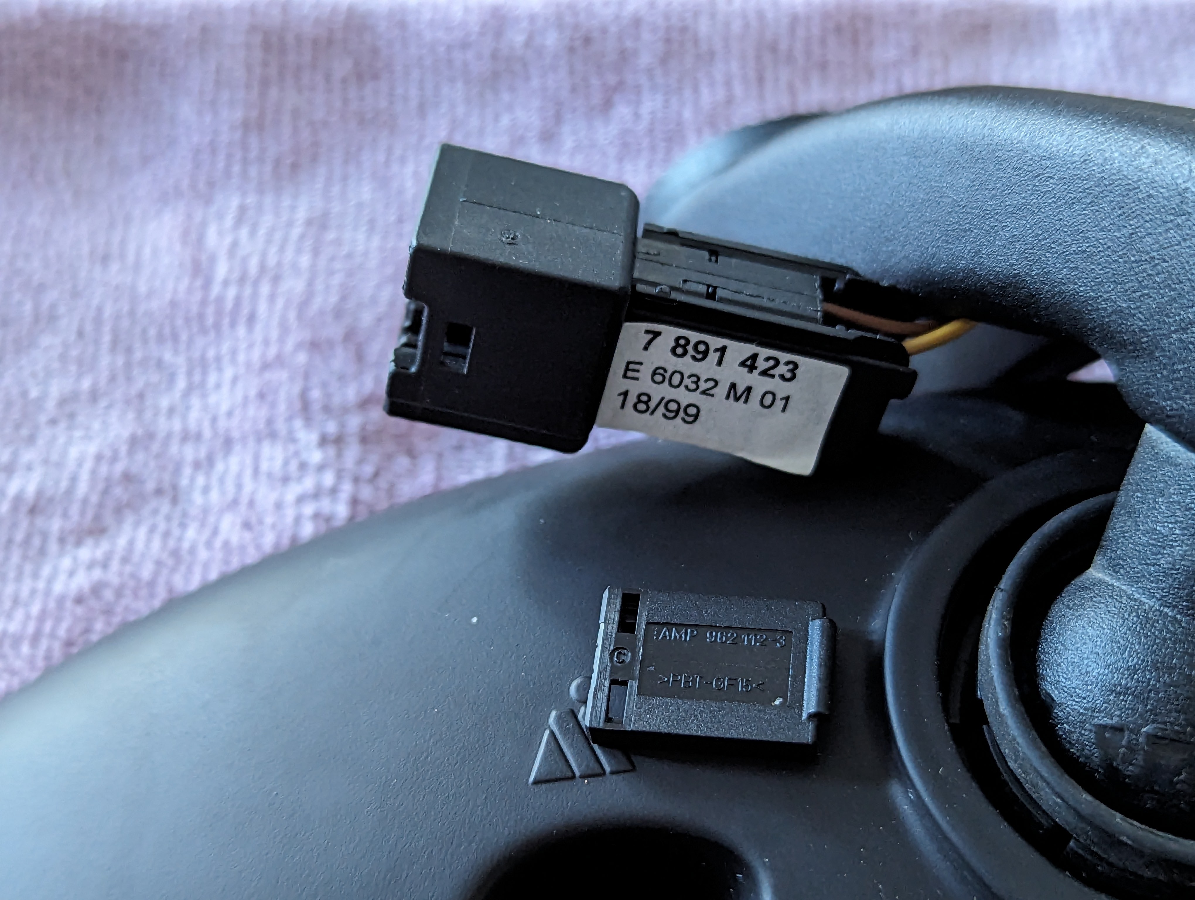
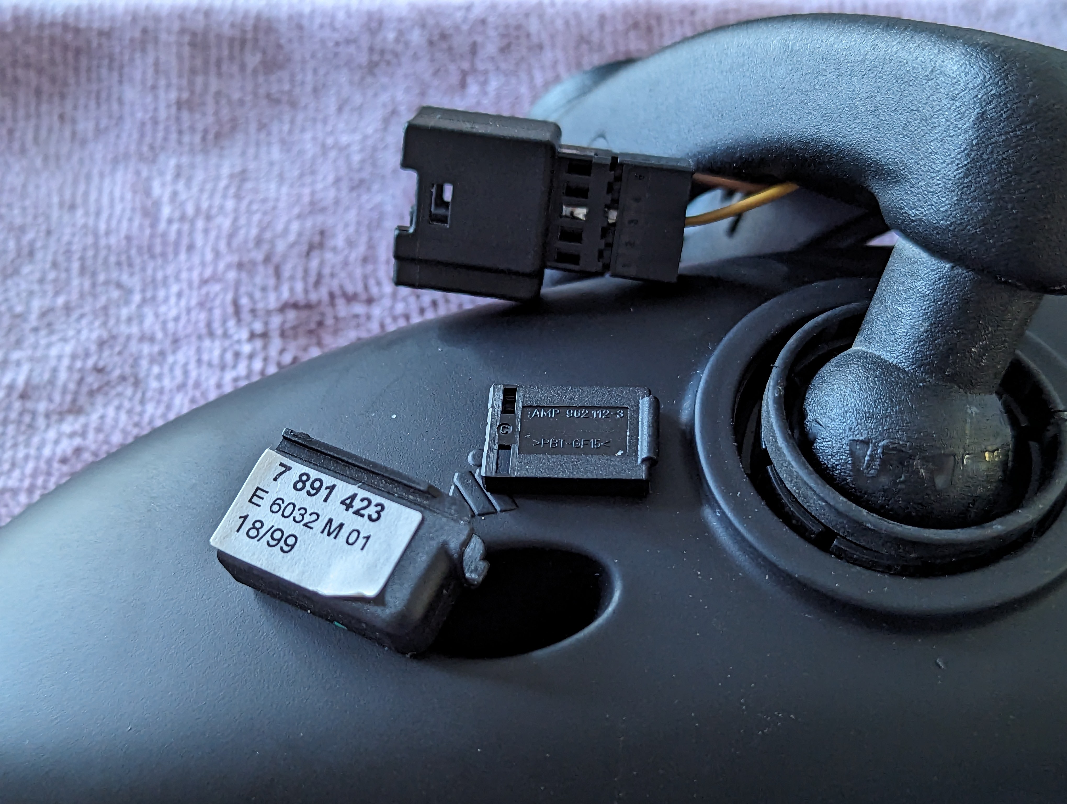
- With the pins exposed, note (photograph) the wire color and pin # for all wiring for your plug.
- Using a pick, depress the prong of each pin and remove it from the plug. This will required depressing it at the fully locked position, and again past the groove for the lock cover. Repeat until all pins are removed and the plug can be set aside.


- Position with glass down and socket assembly accessible. The socket assembly tension is held with a spring clip and will need to be removed.
- Locate the spring clip joint and using a pick pull the ends up and work the clip out of the joint.
- With the spring clip out of position, apply a small amount of alcohol to the ball for added lubrication for disassembly and rotate the ball from the socket joint.
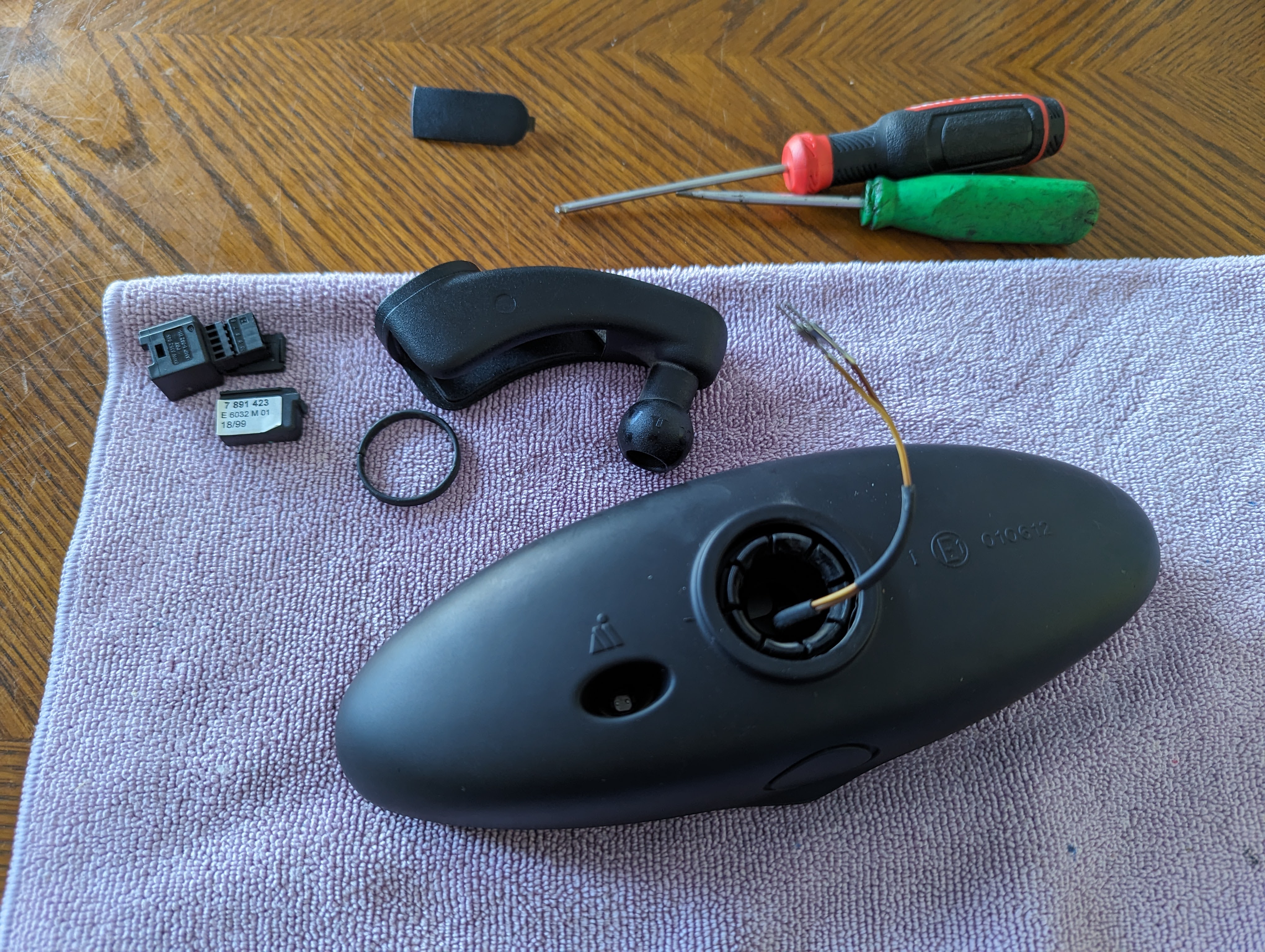
- From the removed stem, remove the 3 each M3 screws and retain the mounting plate, screws, and 3 each spring rods to affix to the DBG stem*
*Note: V1 stems will make right up tight. Due to an error during V2 development the counterbores were undersized and required the removal of the mounting plate bosses by sanding them flush with the plate. Leaving these bosses in place could cause looseness of the spring rods when affixed in place.
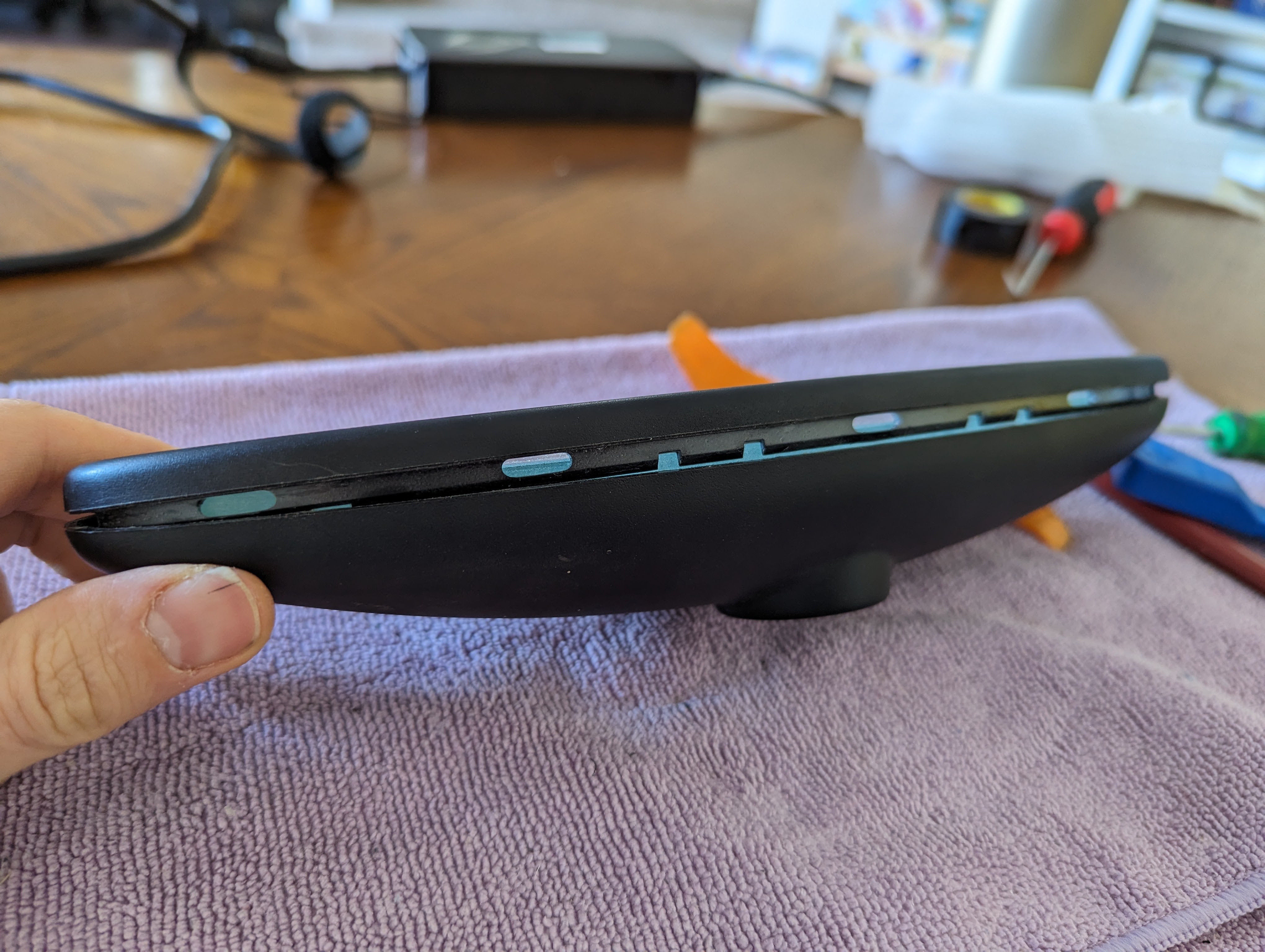
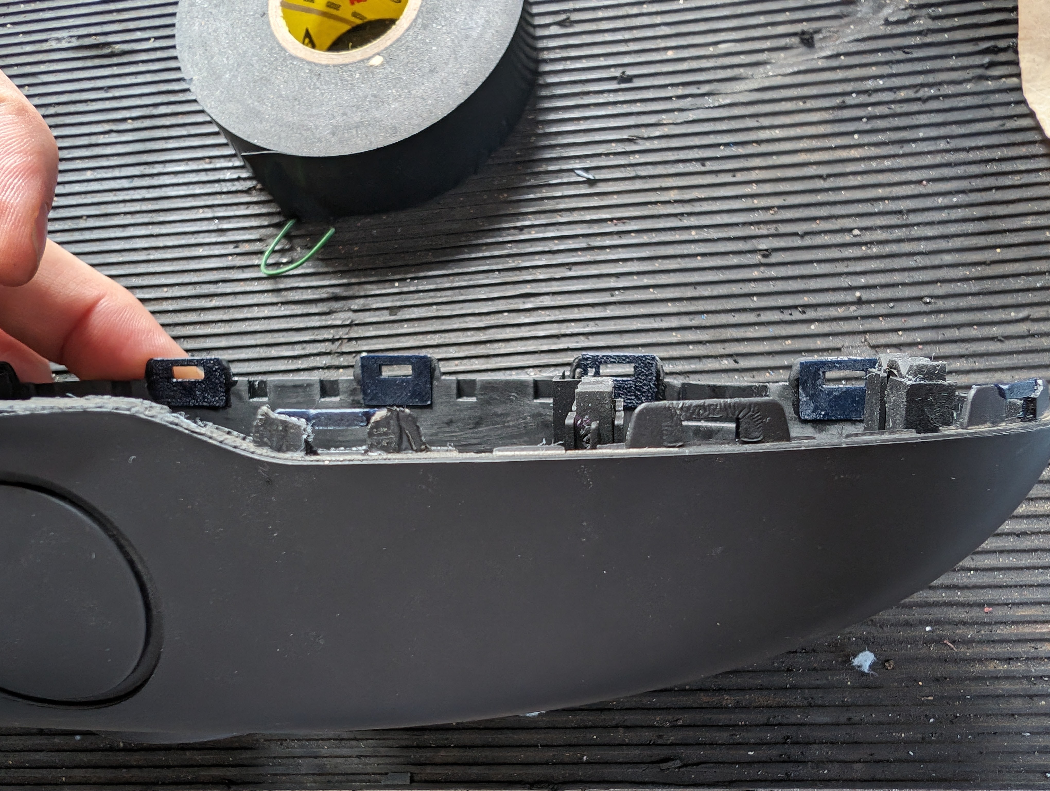
- The two casings halves are held together with a hook and loop plastic tab, in my experience the majority of the loop plastics will be broken on disassembly. Your stem come with repair tabs for these. Using the plastic pry tools, remove the mirror ring from the rear casing around the entire perimeter.

- With the rear casing free, lift and disconnect the connector from the control board.
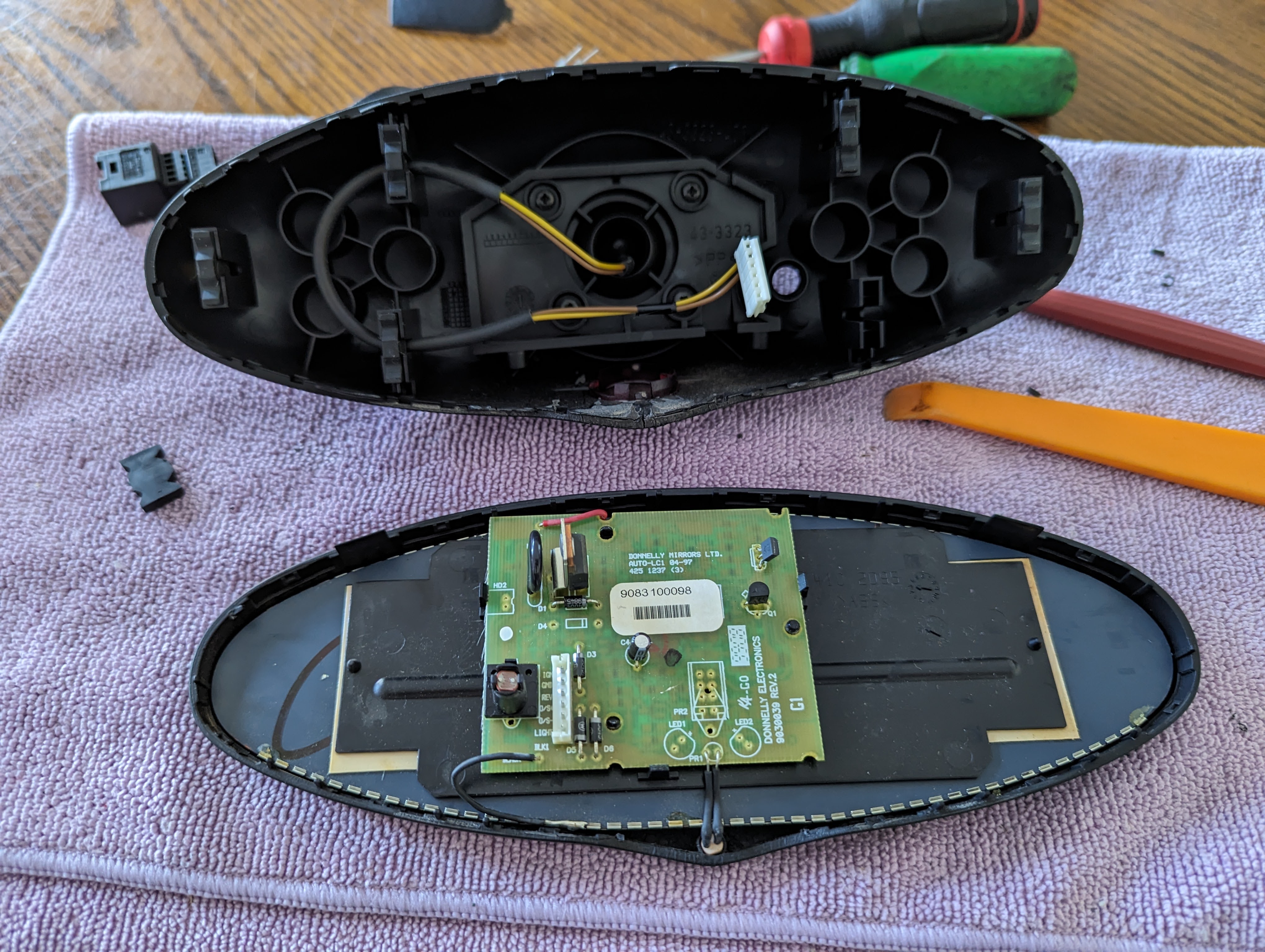
- Note the wire color and position in the plug for reassembly (photograph).
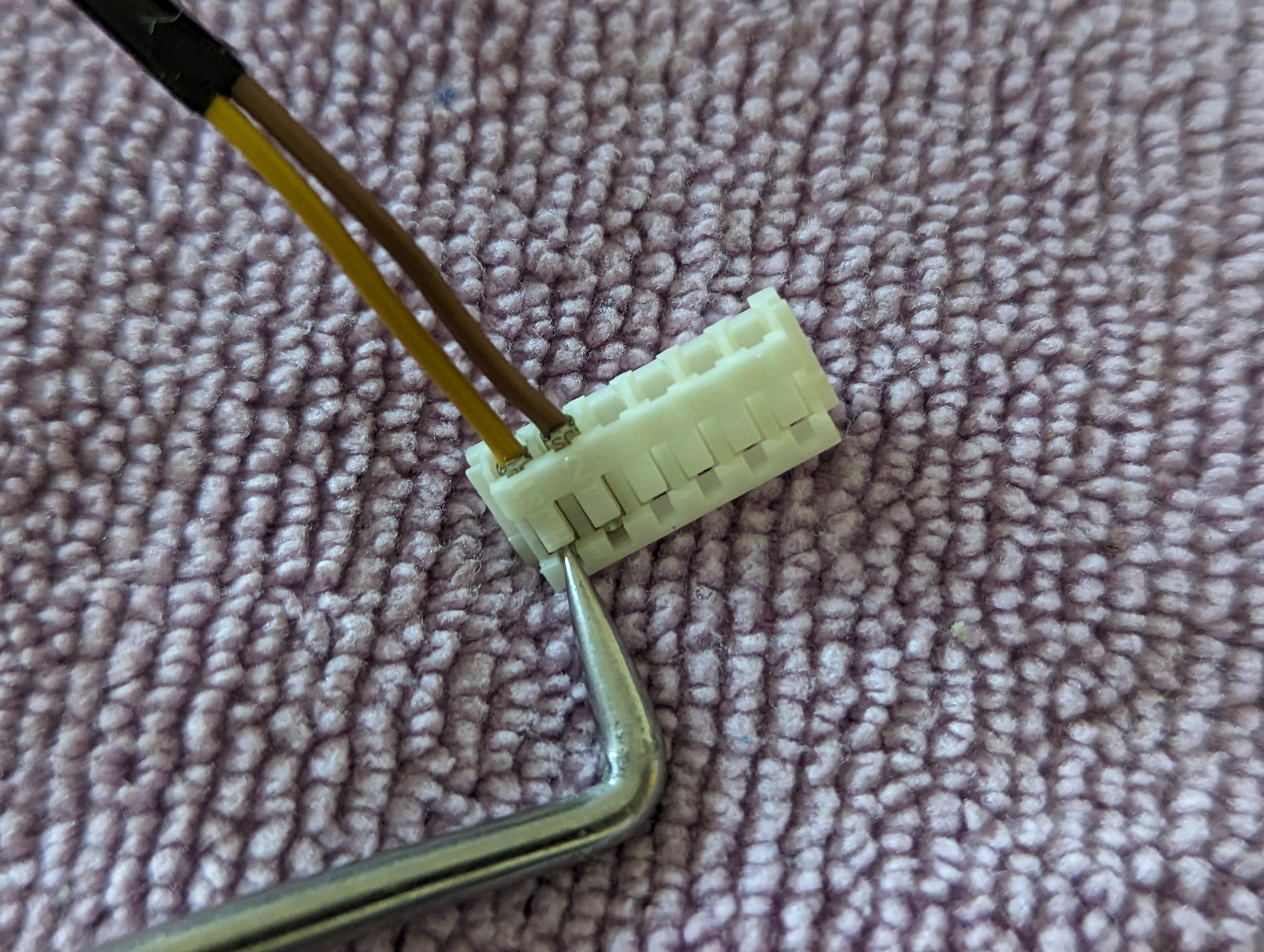
- Using a pick, pry each white retainer clip from the connector up to allow all the pins to be removed.


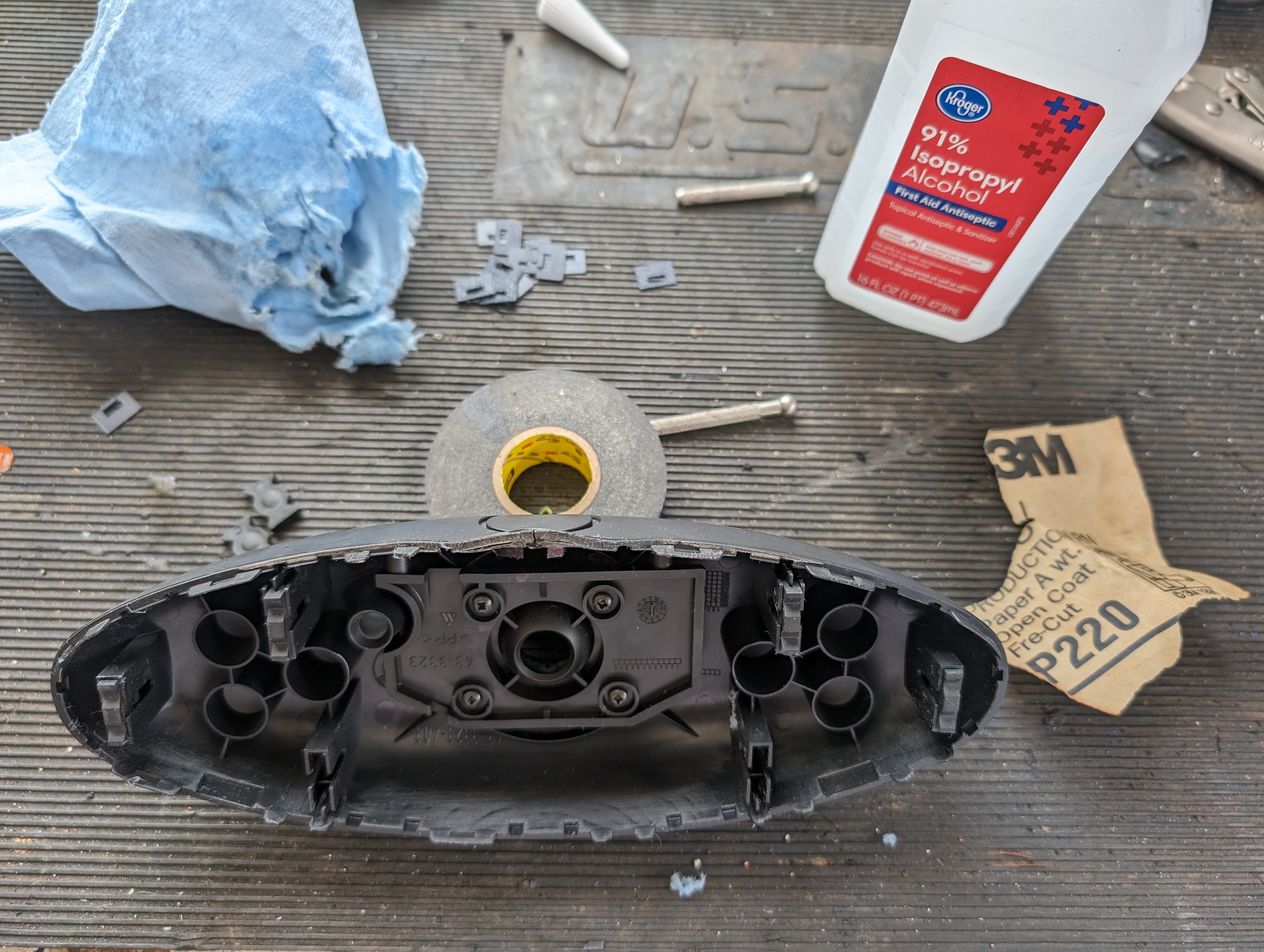
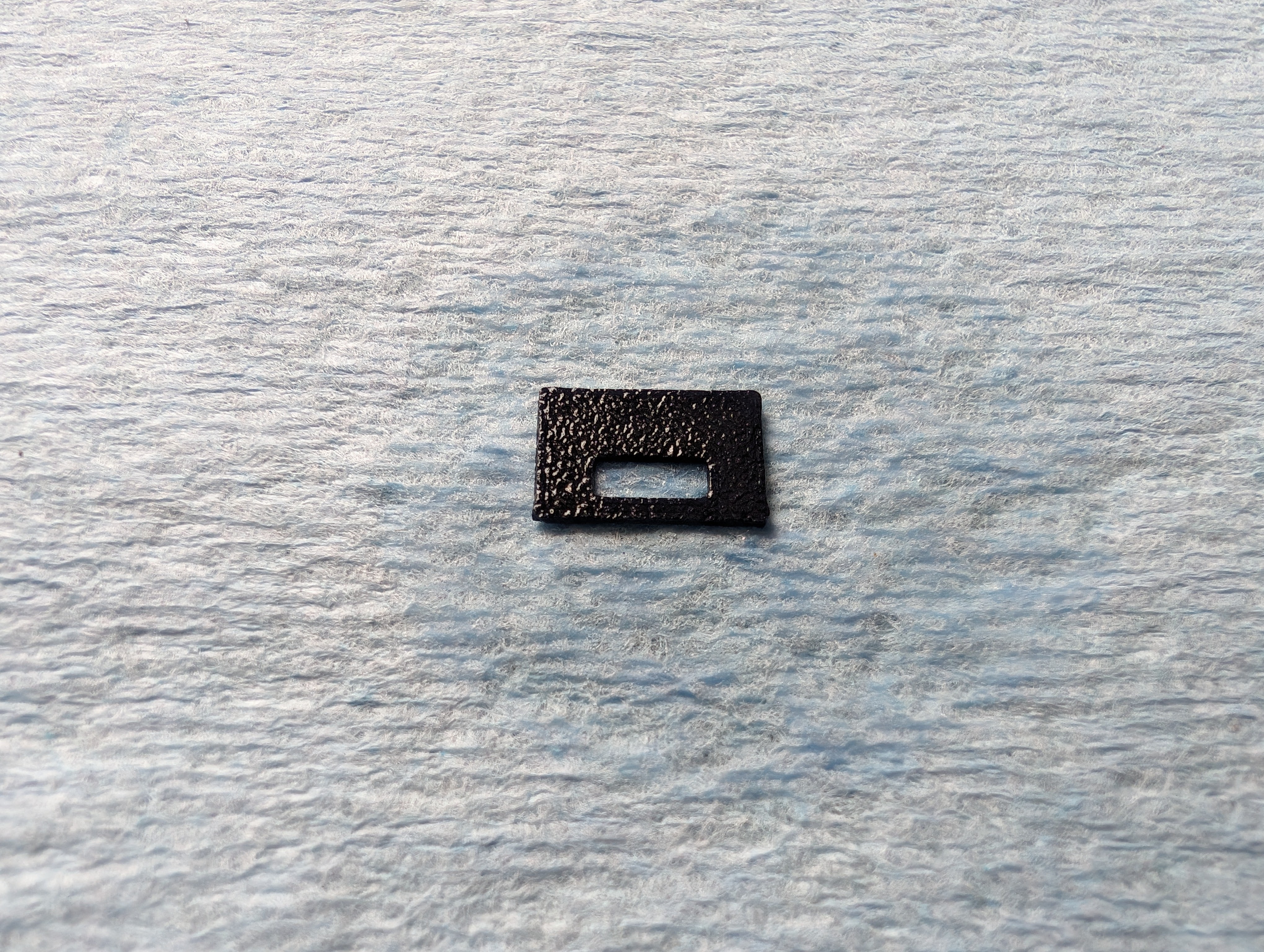
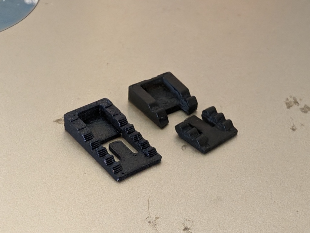
- There are two types of repair tabs based on the condition of the 12 casing tabs after separation. One is a “repair” tab that has the small raised section, the other is a “reinforcement” tab that is completely flat. If the original tab is in place or slightly cracked I applied a reinforcement tab. Else, it got a repair tab. The hole in the DBG tabs are sized to align with the cut outs in the original casing.

- Repair tabs as needed. Lightly sand the casing interior where tabs will be applied and the DBG tab surface to be applied to the casing for a no smooth profile. Wipe with alcohol to clean any dirt/grease/dust. I applied starbond accelerator to each tab, and starbond glue to the rear casing to affix each tab at the 12 mounting points.


- The feeding of the wiring harness through the DBG stem takes some patience. Using an appropriate sized ziptie feed it from the ball to the exit port at the top of the DBG stem. Note the orientation of the zip tie in the internal passages. The wiring should be taped to the “zip” size of the ziptie for easiest installation.

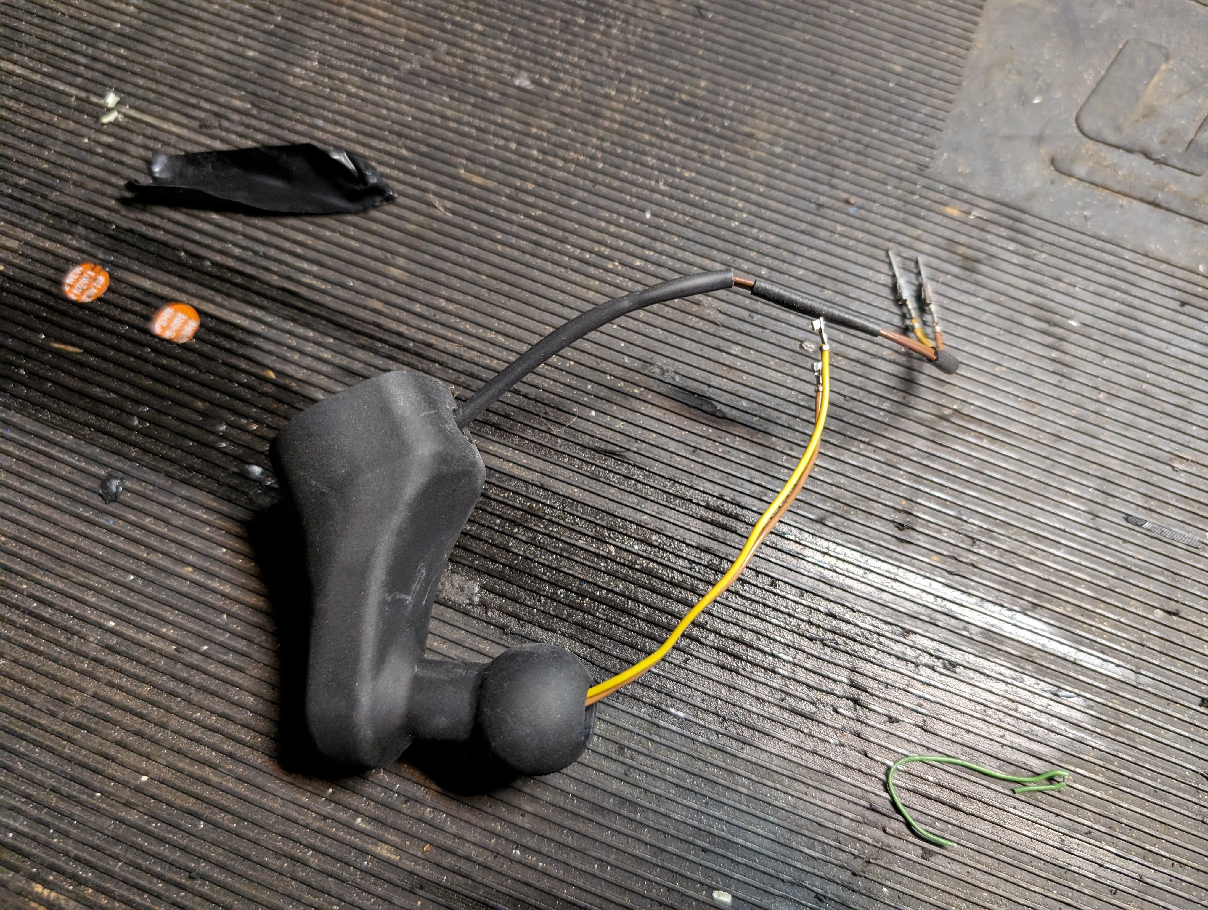
Note: Care should be taken when feeding the wiring through the internal passages. Due to the machining operation it is expected the internal corner is relatively sharp and could cause wire casing to be chafed if not installed with care.
- I lubricate my wraps with a bit of alcohol to aid in feeding them through the passages but this also affects the tape adhesion so use at your discretion.
- Install the DBG mirror stem into the socket in the rear case. During installation, ensure the tool socket (or other material) is supporting the mirror ball socket to ensure pressure from the stem installation is directly translated to your workbench and not through the socket support structure/rear case. Ensure wiring is not being pinched or damaged during installation.
- Reinstall in reverse order of disassembly referencing the photos/notes of wiring positions when making up connectors.
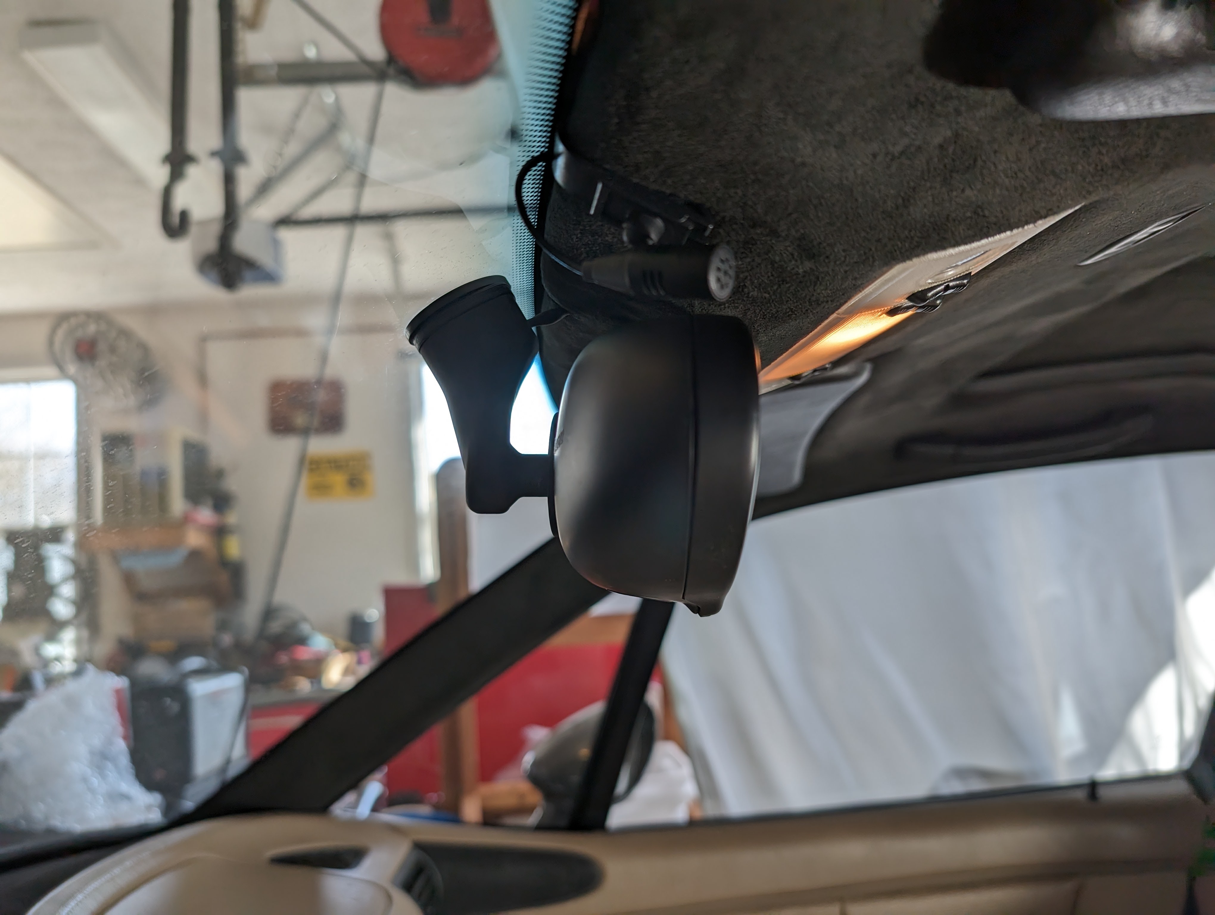
- When installing the autodim back into the car the plug will require to be tucked into the headliner edge.

Leave a comment