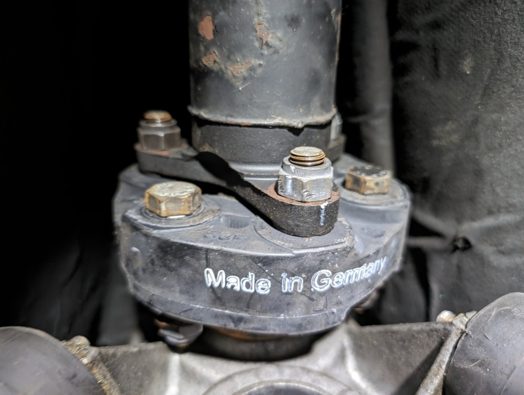
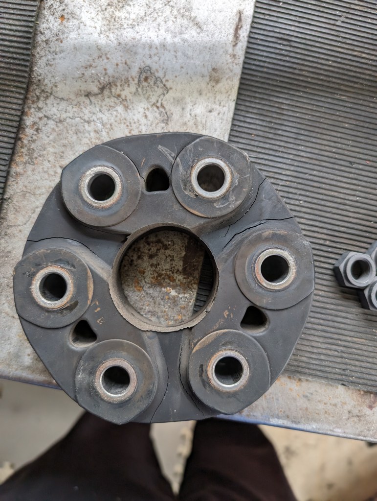
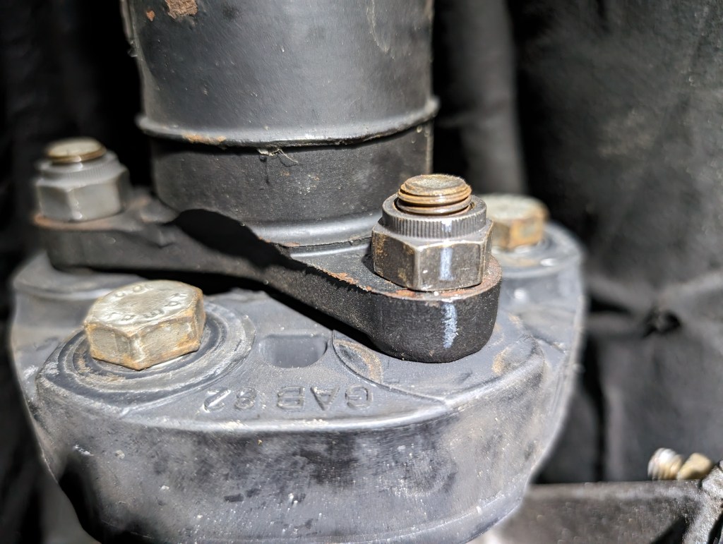
While working on my exhaust fabrication I noticed my giubo [a.k.a. flex disc] was starting to separate. I thought I had replaced it when I did my clutch when I first bought the car back in 2013 but I cannot find a record of it and the fact that it came out with a BMW logo on it I suspect I just reinstalled my original when I put the transmission back in.

As simple as this job seems, there’s a few trick to it that make it more successful if followed. Specifically the giubo is marked to which side the flanges should be installed on, and a good mechanical joint should only be torqued on a metal surface and not on the bushing face. Since I had to replace mine and as pictures will show that 11 years ago I didn’t know any better I figured I’d make a up to date DIY for this well documented process and how I accomplished it.
I ordered a Febi (OE supplier) giubo and at the time of writing this is ~%50 cheaper than the OEM BMW branded one, you can use your own judgment of which you want to order based on the following photo:
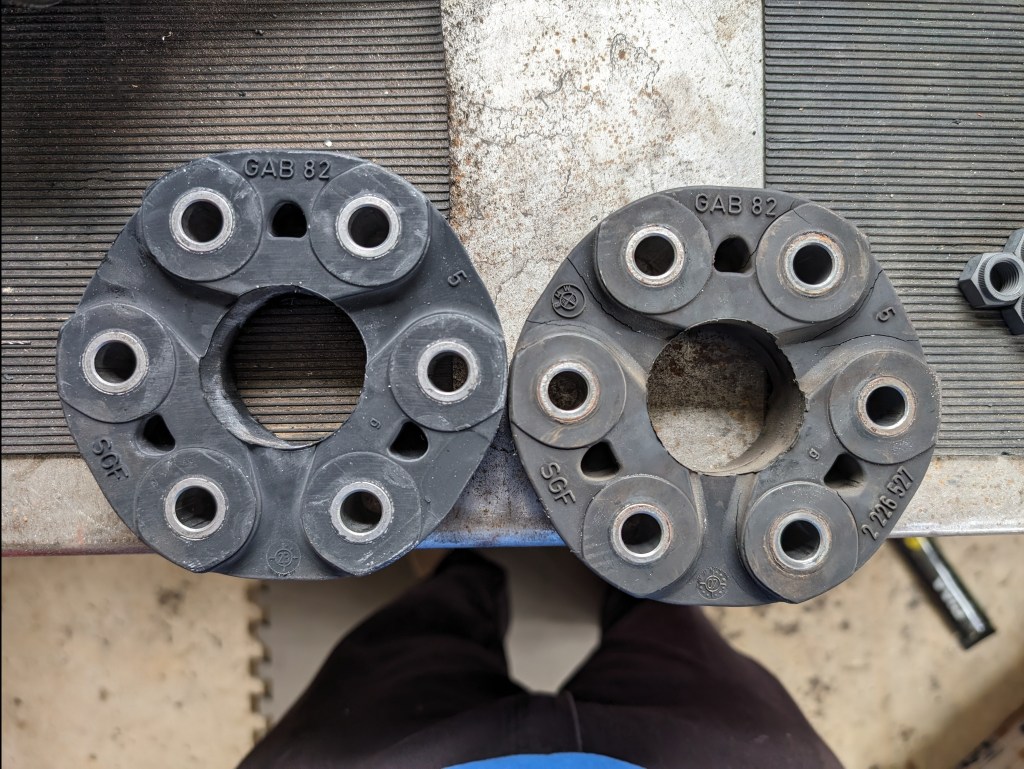
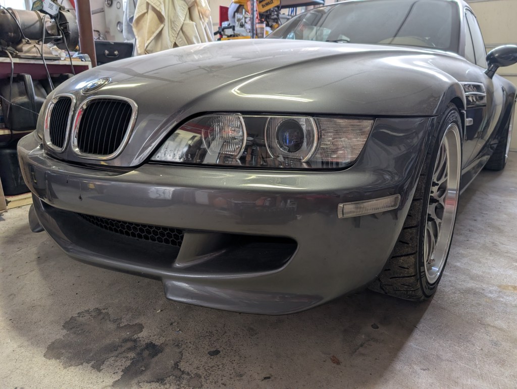
The following is written for a S52 Z3M application, but likely cross references well across most 6 cylinder BMW of the era. Please verify your PN and application for parts prior to ordering.
Material:
- Giubo (obviously) – 26112226527
- Giubo nuts (single use, self locking) (6x)- 07129900047
- Exhaust midpipe consumables (removed as interference) –
- FWD flange gaskets (2x): 18301716888
- AFT flange gaskets (2x): 18111723379
- Exhaust midpipe contingent material:
- FWD joint hardware:
- M10 nuts (single use, self locking) (6x): 18301737774
- AFT joint hardware:
- Bolts (M8X55-8.8) (4x): 07119902957 (conditional)
- M8 nuts (single use, self locking) (4x): 11621744323
Tools:
- 18mm wrenches, Two minimum, one ratcheting is highly recommended
- Torque wrench (25 & 100 Nm)
- Wrench extender
- Wax pencil
- 10mm socket
- 13mm socket
- 17mm socket? I don’t have the stock exhaust flanges anymore but I think the manifold nuts are 17s
- Socket wrench/electric option
- To start, get the car up and supported in a safe manner
- Remove the midpipe- Disconnect the post-cat O2 sensors at their plugs that are tucked under the driver side edge of the heat shield and unclip their wiring to allow removal of the midpipe. Break the FWD and AFT flanges and remove carefully.
Caution: Use care when handling the midpipe with the O2 sensors installed, they have ceramic heater elements that are prone to breaking and throwing OBDII codes and are hella expensive.
- To access the Center Support Bearing (CSB) the midpipe heat shield will need to be removed. Undo the body nuts with the 10mm socket and store the nuts and shield out of the way. I took the opportunity to deep clean this part from my recent oil leak when all the gunk was not raining on me under the car.


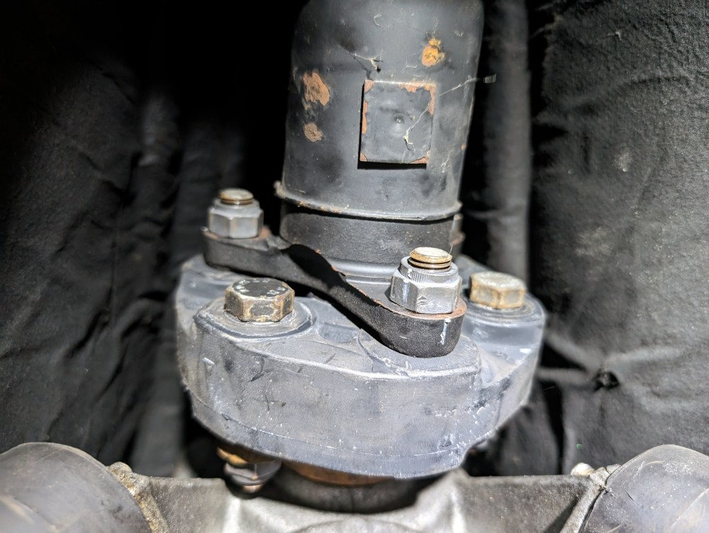
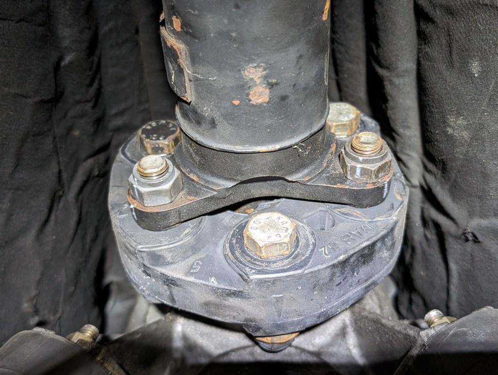
- As previously pictured, at removal I now know that half of these fasteners are installed incorrectly for a proper giubo installation. Remove the nuts and bolts (as possible) to disconnect the giubo from the transmission and driveshaft flanges. To fully remove the giubo the two nuts holding the CSB must be temporarily removed to allow the manipulation of the driveshaft to replace the giubo.
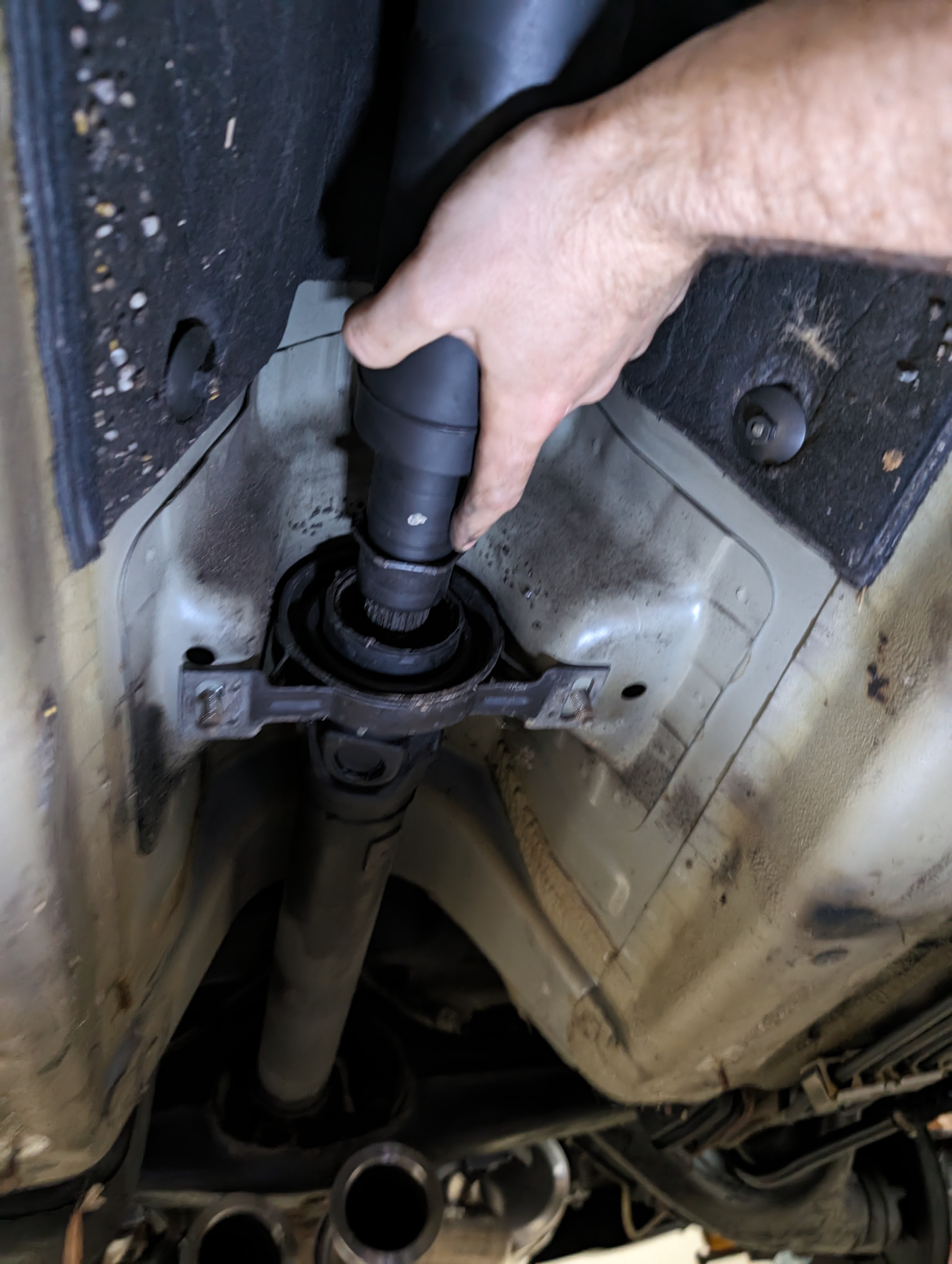
- Take note when installing the new giubo that the OE giubo is marked with arrows about its periphery. The arrows (and bolts!) should point towards their mating flange face. Prior to putting the giubo in place, the 3 bolts for the driveshaft flange must be preloaded as there is not sufficient clearance to the transmission casing to fit in place.


- With the giubo in position, reposition the drive shaft and loosely resecure the CSB. Do not torque these nuts at this time it should be allowed to move while the giubo joint is made up.
- Install the remaining giubo hardware, 3 additional bolts and all nuts. Using the two wrenches, make each set up to a wrench tight condition. The nuts are mechanical lock nuts and will be tight once they engage their locking feature, however there should be a significant effort change when the nuts and bolts are made up tight. DO NOT TORQUE past the wrench tight (snugged) condition at this time.
Note: A bolted joint assembly should always be torqued on the nut side of the joint. The nut should also be on the metal surface for torquing when making up a bushing (which is why you should alternate the bolt orientation) for the proper application of torque.
- Since it’s impossible to easily get a torque wrench on the nuts on the transmission flange, I applied a “torque by rotation” method. Before applying the required torque, I marked each nut with a wax pencil. I applied the 100Nm of required torque to the 3 available nuts and averaged the rotation shown to apply similar force to the nuts on the transmission side with a pair of wrenches. My application required approximately 1 full flat rotation past my wrench tight condition. During torque application of nuts, the bolts should be restrained to the maximum extent possible to prevent rotation. With the known rotation of the 3 nuts accessible with a torque wrench, I used my pair of wrenches to rotate the 3 transmission nuts to the similar 1 flat past wrench tight. (My application was made more complicated as I had one axle removed and could not use my parking brake to prevent the flanges from rotating, it is not recommended)

- Once the giubo is made up completely, torque the CSB nuts to 25Nm
- Reinstall interferences in reverse order using new software for the midpipe, and hardware as required.

Leave a comment