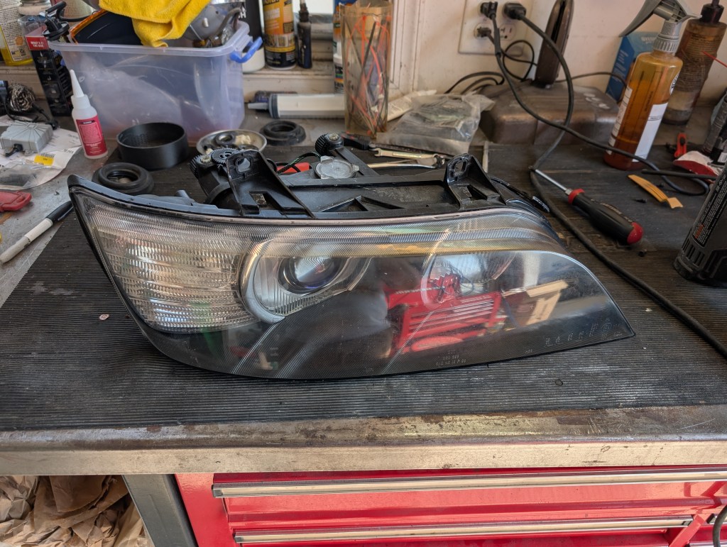
The following is written for Z3 facelift (4/99+ MY, chrome ringed inner lens “face lift”) headlight retrofit using a “full” DBG retrofit kit and Morimoto BiLED 2.0 Projectors. The -4/99 MY headlights have a GLASS inner lens (“non-facelift”) and require updating to the chrome ringed lenses or your own solution to address the low beam cover (aftermarket shroud or special tooling to maybe successfully cut the glass lens). Please verify your application for part identification prior to ordering and feel free to email me with any specific questions not answered here-in. Use the following as a guide at your own risk.
Material:
- DBG retrofit “kit”
- Morimoto Bi-LED 2.0 (PR352) kit
- Optional- DBG chrome ring hole drill guides
- Optional- DBG LED shroud
- Optional (highly recommended) – DBG fixed pivot repair kit
- Isopropanol alcohol
- Tri flow lubricant
- Small zip ties
- General purpose cleaner (I use Window cleaner)
- Starbond CA (Thick) glue (contingent)
- Starbond accelerator (contingent)
- Cerakote headlight polish kit (optional)
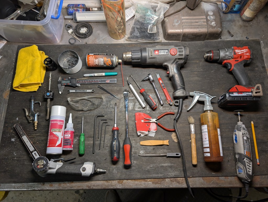
Tools:
- Soft bristle brush
- Compressed air source
- Micro fiber towel
- Heat source (oven or heat gun)
- Large Pry tool (broad tip)
- Small pry tool
- Small plastic pry tool
- Small razor knife
- Torx-bit T-10 size
- Box wrench (7mm)
- Dremel with cut off wheel
- Caliper (Digital & mm’s suggested)
- Eye & Respiratory PPE
- Allen wrenches (Sizes 2, 4, 5, 6 mm)
- #2 Phillips screw driver
- Drill
- Drill press (optional)
- Drill bits (9/64” & 11/64”)
- Finger sander (optional)
- File
- Hole saws (1.5” and 3.25” diameter with ¼” pilot drill size arbor)
- Small pliers
- Deburring tool
- Sand paper
- Pencil
- Sharpie marker
- Belt sander (optional)
- Right angle pick (for non facelift lens removal)
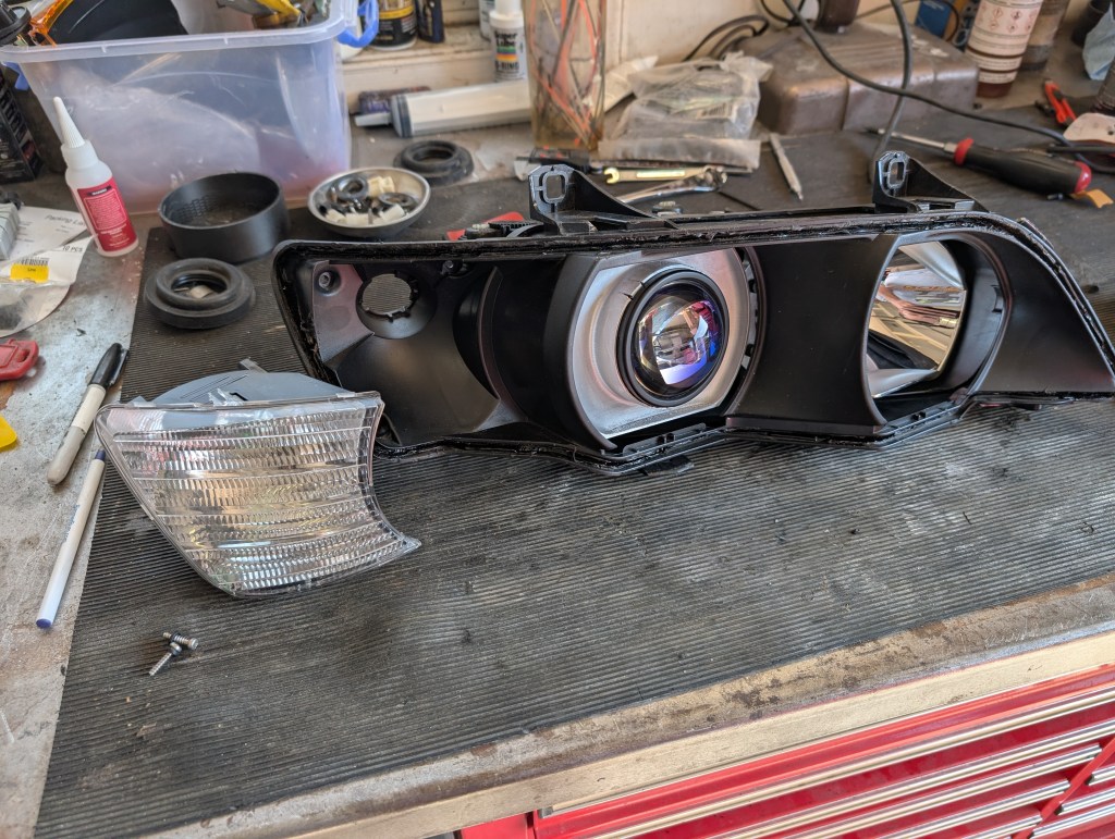
To start, I’ll clarify some of the terms I’ll use refencing pieces throughout this DIY. The Z3 headlight housing is comprised of a bunch of pieces.
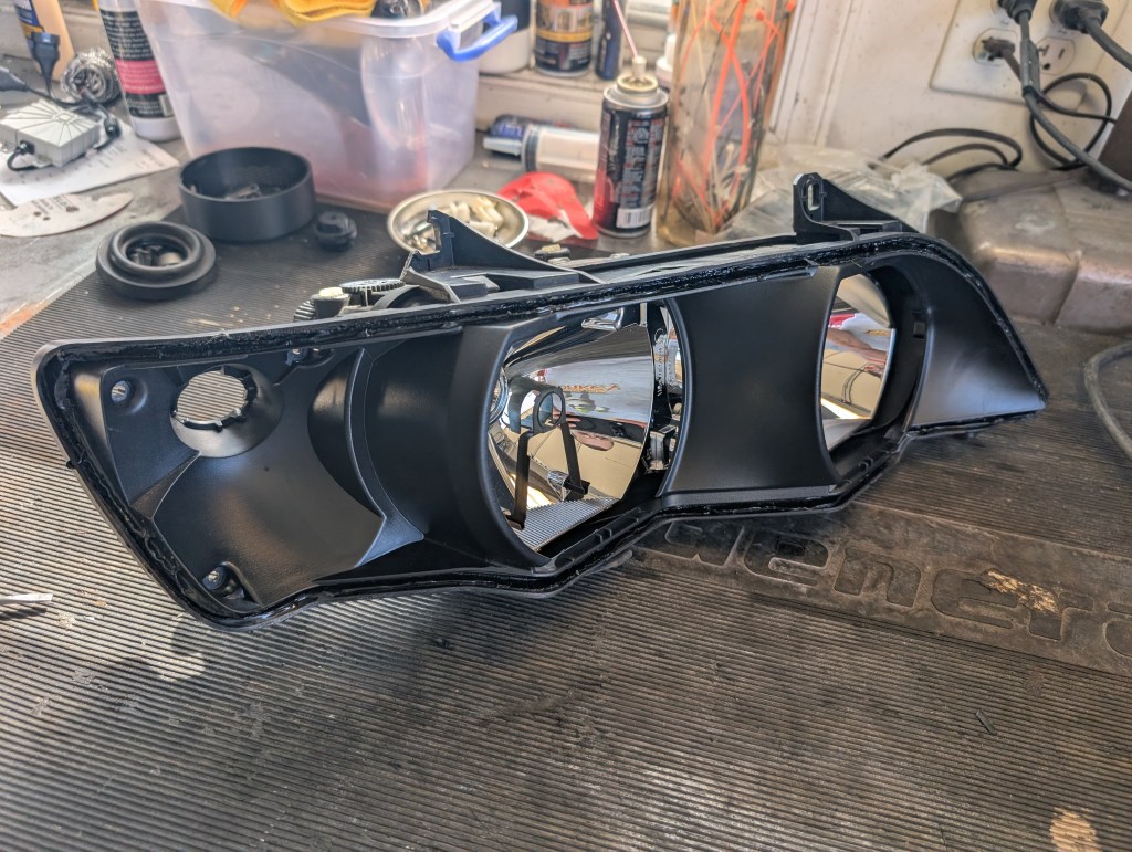
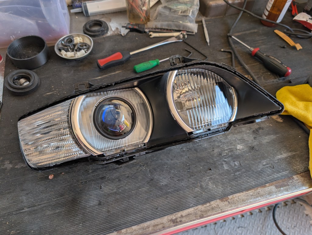
a) The headlight itself is comprised of three major sections: The outer lens, the middle housing, and the rear housing
b) The middle housing holds the turn signal and the inner fluted lenses and is what attaches to the car via the 4 mounting points. The inner lenses will be referred to the inboard lens (original high beam) and the outboard lens (original low beam).
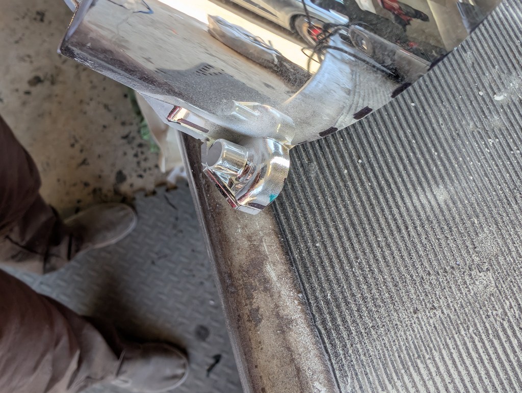
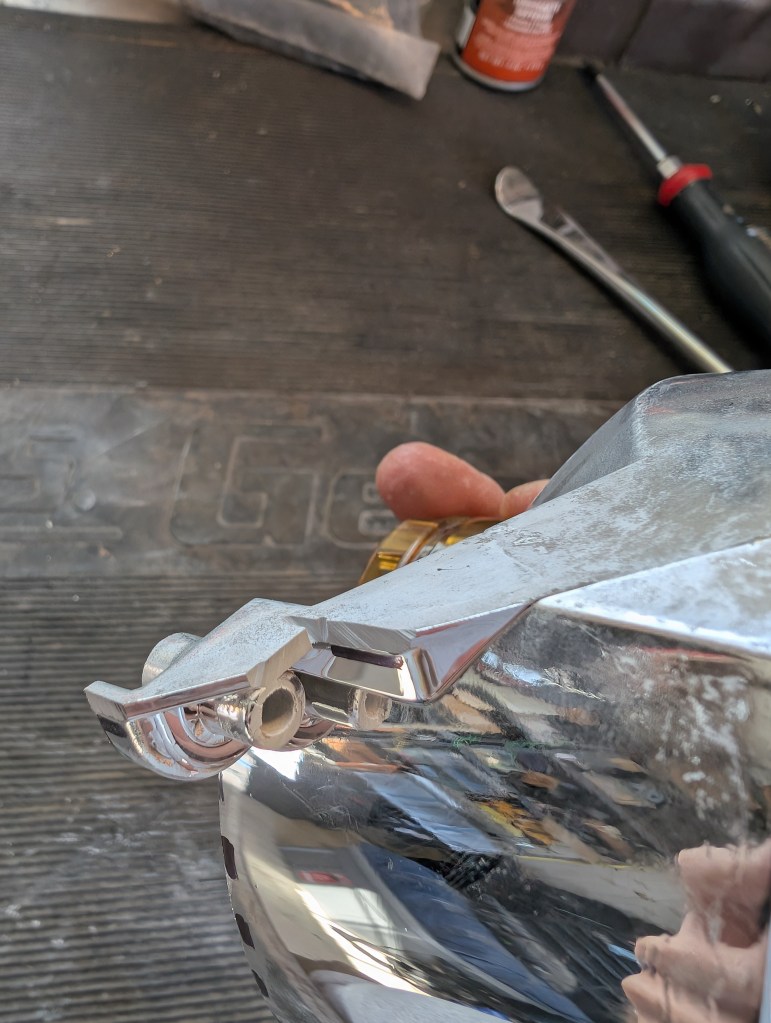
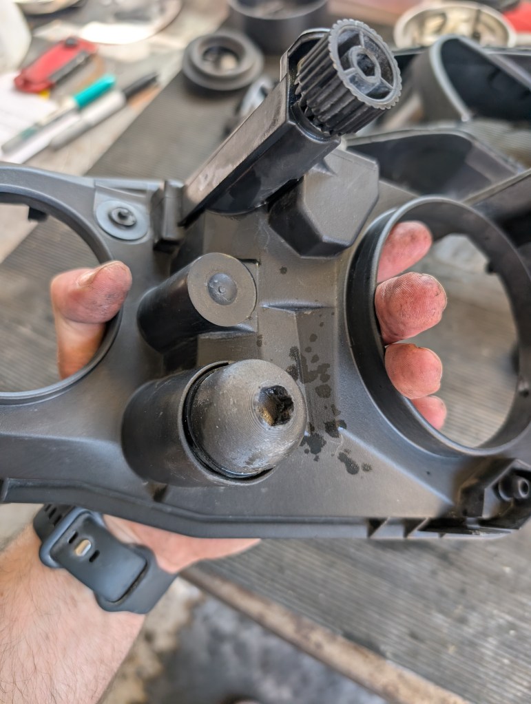
c) The rear housing holds the original bowls assembly and starts as a single piece and the aiming mechanisms. The high beam bowl (will be cut out/modified and reused) and low beam bowl (will be cut out and discarded). The bowls are mounted to the rear housing via three ball & socket joints to allow aiming of the headlights in the car. There are two between the high beam and low beam bowls. The lower one I refer to as the “fixed pivot” and is typically its mount to the rear housing is always broken or will break during this retrofit if you look at it too sternly. The upper one is up/down aim adjuster. The third is located on the outboard upper corner of the low beam bowl and serves for the left/right aim adjuster.
With all that out of the way, let us begin.
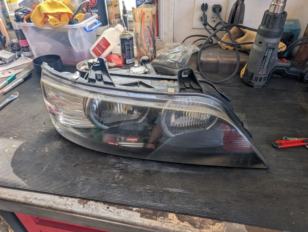
Pre disassembly cleaning:
We’ll start by giving the headlight a good cleaning, it will be handled a whole bunch and working with a dirty/dusty housing just sucks. A healthy coating of cleaner and thorough brushing to remove all of that caked on junk to start. After wiping up with your favorite towel, blow dry the hard-to-reach areas
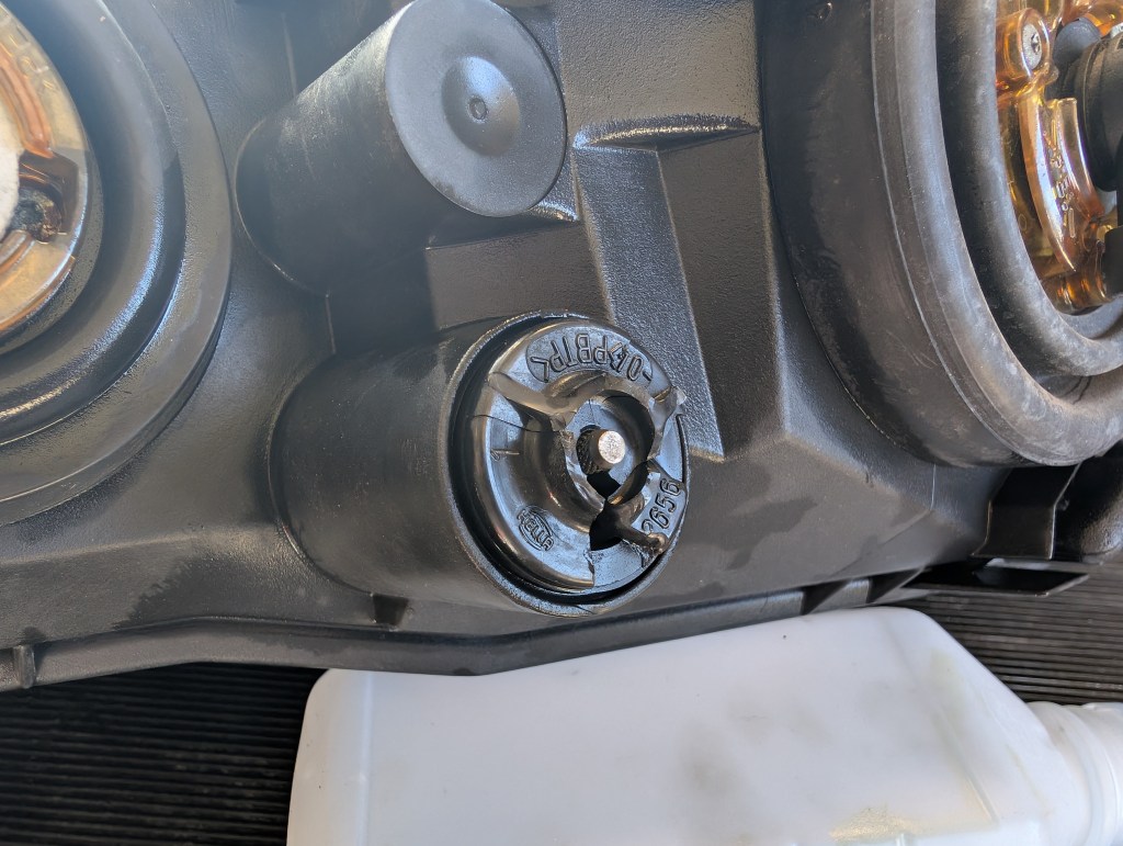
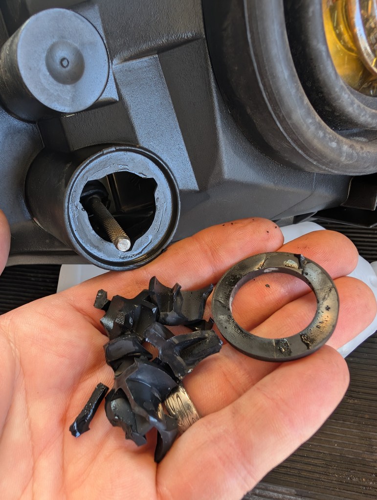
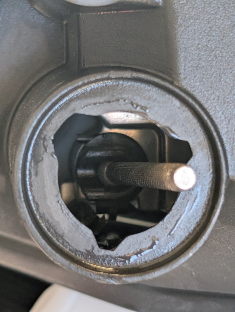
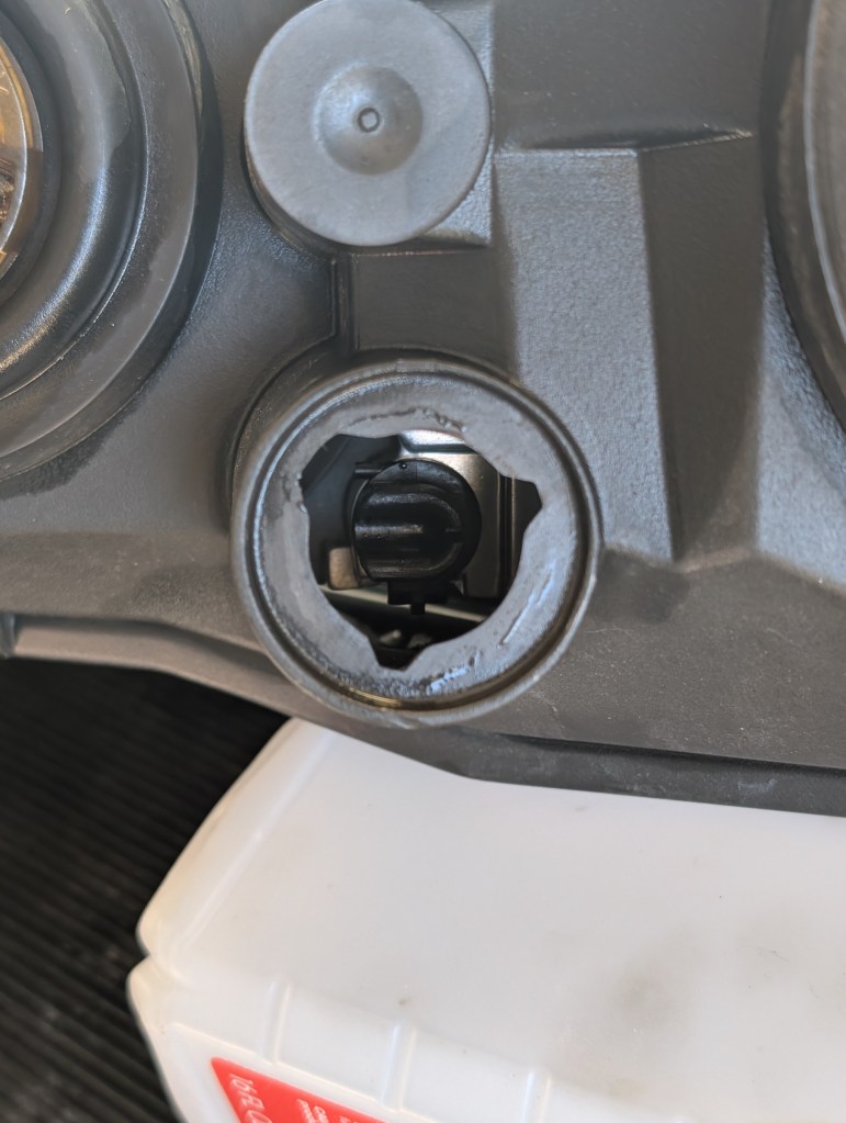
Fixed Pivot repair/replacement:
If the headlight fixed pivot mount is already broken/breaking or you plan to replace it anyway for future proofing, it would be smart to go ahead now and finish removing the remains and collecting the o-ring and knurled ball fixed pivot. These two pieces will be reused in conjunction with the DBG pivot repair kit. The Pivot repair epoxy has a 12-24hr cure time, instructions for the Pivot repair are here .
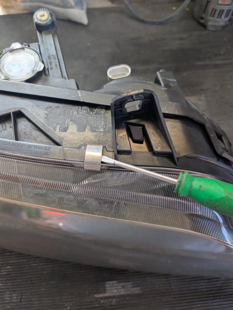
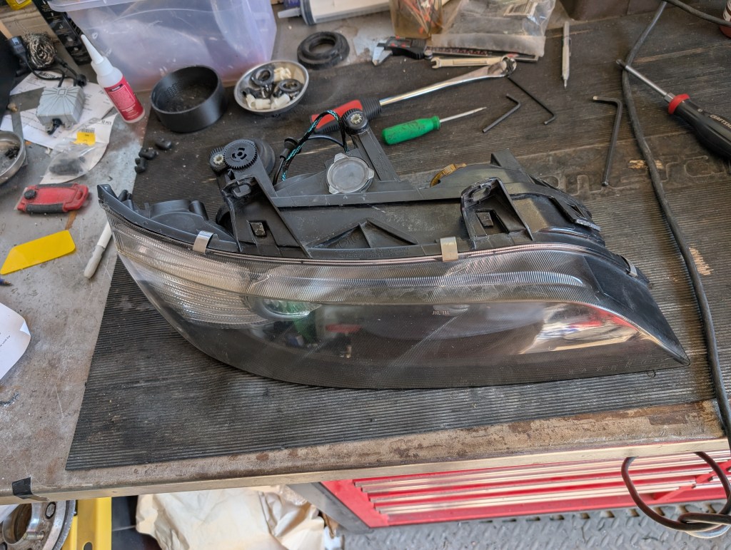
Removal of outer accessories:
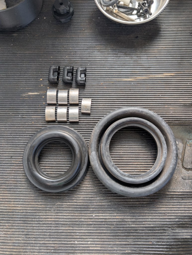
The three headlight sections are “clipped” together with seven spring clamps, using your small pry tool, remove and store the seven clips for reuse after final assembly. We’ll also want to remove the three “breather filters” attached to the rear housing (at the outboard upper corner of the turn signal, the inboard upper corner of the high beam, and the bottom of the low beam) and the high and low beam rubber weather boots. The low beam boot is not needed for re-use.
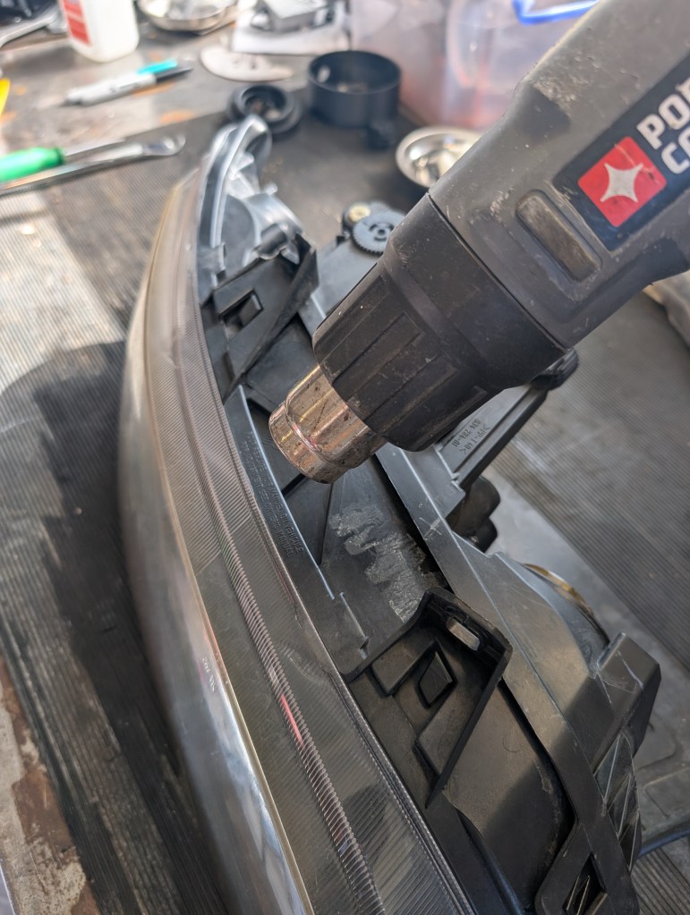
Heating of the headlight:
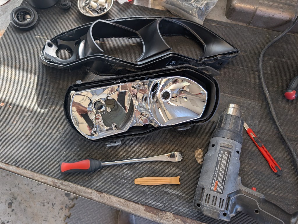
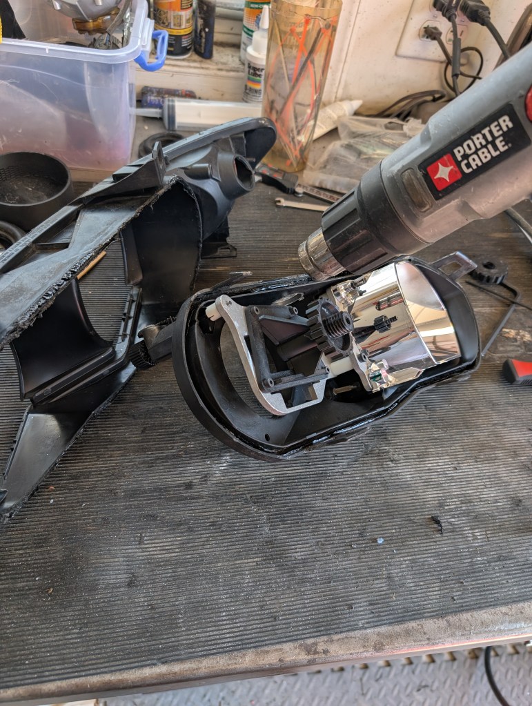
The three headlight sections are “glued” together with butyl sealant. Heat is needed to soften the butyl and allow them to be separated. I prefer use of a heat gun currently, but have used an oven in the past.
- heat gun method: to limit/direct the application of the heat, and keeps the majority of the parts cool enough to the touch to not need gloves while working the piece apart. The two biggest concerns with the heat gun method are its slower (15-20 minutes per joint) and has a higher risk of “burning” if you don’t keep it moving or get too close.
- Oven method: The alternate heating method to soften the butyl (and I’ve used in years past) is placing the entire headlight in the oven on the lowest temperature setting for 10-ish minutes. Using the oven method I’ve also accidently melted connectors as they got too close to a heat source and they require gloves to handle after heating the entire assembly and baking plastics in your food oven unless you have a dedicated garage oven large enough.
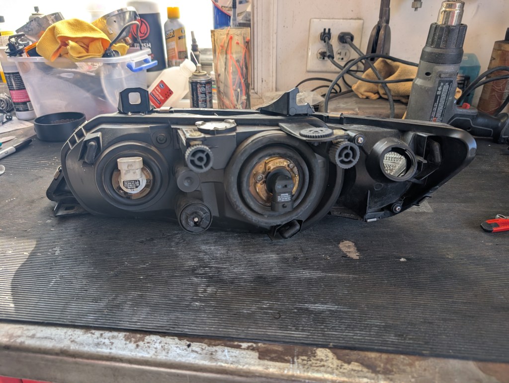
Headlight disassembly:
After heating the joints need to be disassembled, the below is written as if using the heat gun method, but should be comparable to oven use.
Caution: For the outer lens removal, you’ll want to focus the heat more directly to the middle housing black plastic as the clear lens burns faster.
Caution: When using the pry tool avoid twisting at all costs. Twisting will point loads the corners/edge of the tool into the warm plastic and will mar the headlights. Keep the pry tool as perpendicular as possible when prying evenly with the most contact surface as possible.
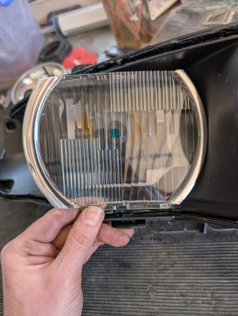
Caution: For facelift inner lenses, during disassembly avoid the butyl contacting the chrome rings. ANY butyl contact with the chromed section will pull the chrome coating off the plastic lens.
- For each joint at disassembly, I do a few minutes (5-7ish) of general overall joint heating to warm the entire perimeter of the joint up. There is a noted smell that begins to present when the butyl is getting soft enough.
- For the outer lens to middle housing, I start on the bottom of the headlight and add more focused heat on the lower edge and around the lower corners to begin checking for butyl release. After a few minutes of focused heat I’ll check with my large pry tool if the joint is starting to move. Once the joint begins to move I’ll work the lower edge until the joint doesn’t want to move any more. Moving around the headlight perimeter in the inboard direction to get around to the top, continue focused heating and prying, the hardest area to release is the corners/lip in the turn signal area these should be saved for last. Reapplying heat as necessary to soften the butyl. Once the rear lip off the outer lens begins to clear the forward groove of the middle housing, the butyl will “string” as the two parts separate, either cut the strings with a razor knife or hit them with a heat gun to break them to avoid a messy separation.
- Once removed store the outer lens in a safe place for future reuse.
Caution: The chrome coating is extremely delicate. Avoid any direct contact/chemicals/direct wiping on the chrome surfaces. I have not found a good repair method of the chrome coating at this time. I cannot stress this enough
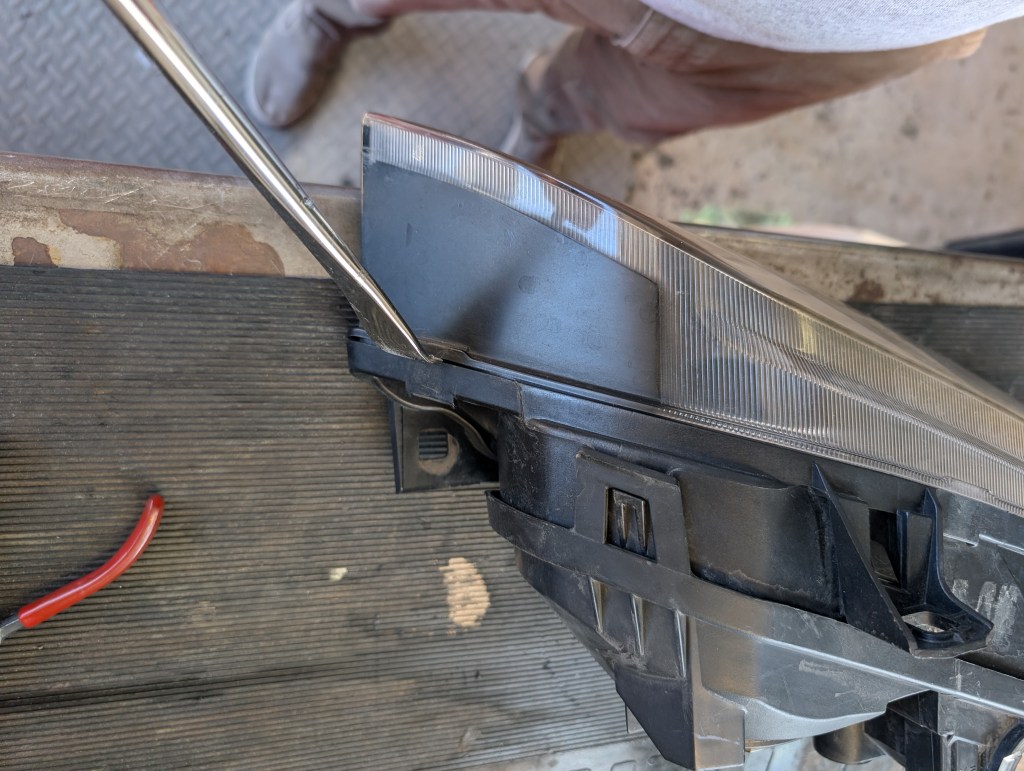
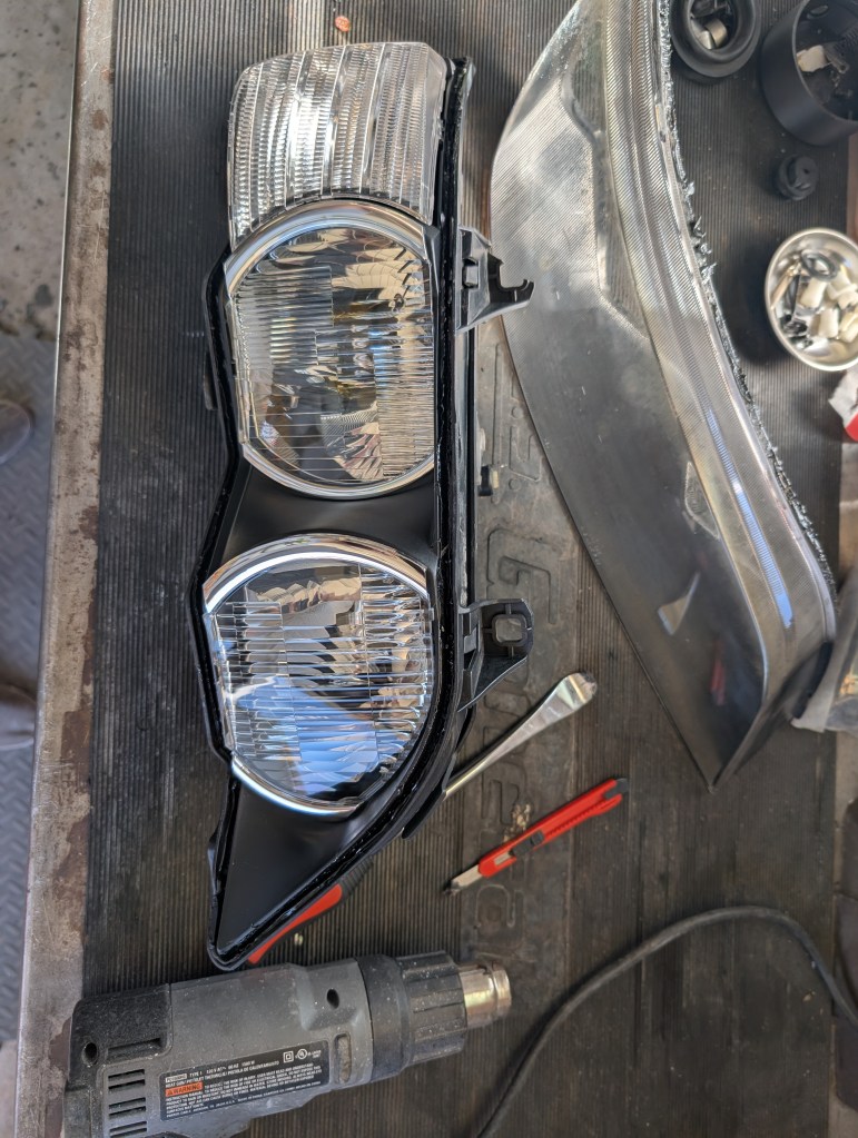
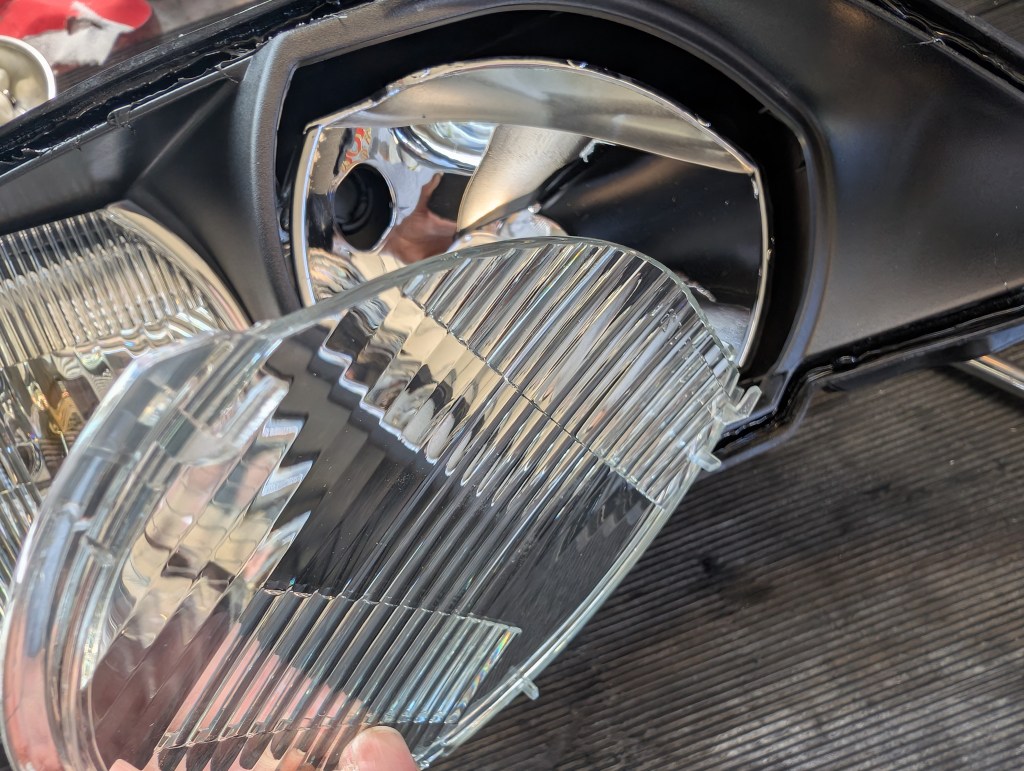
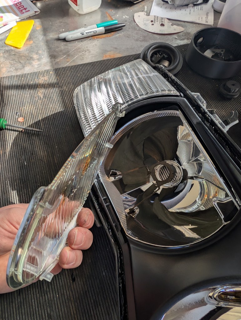
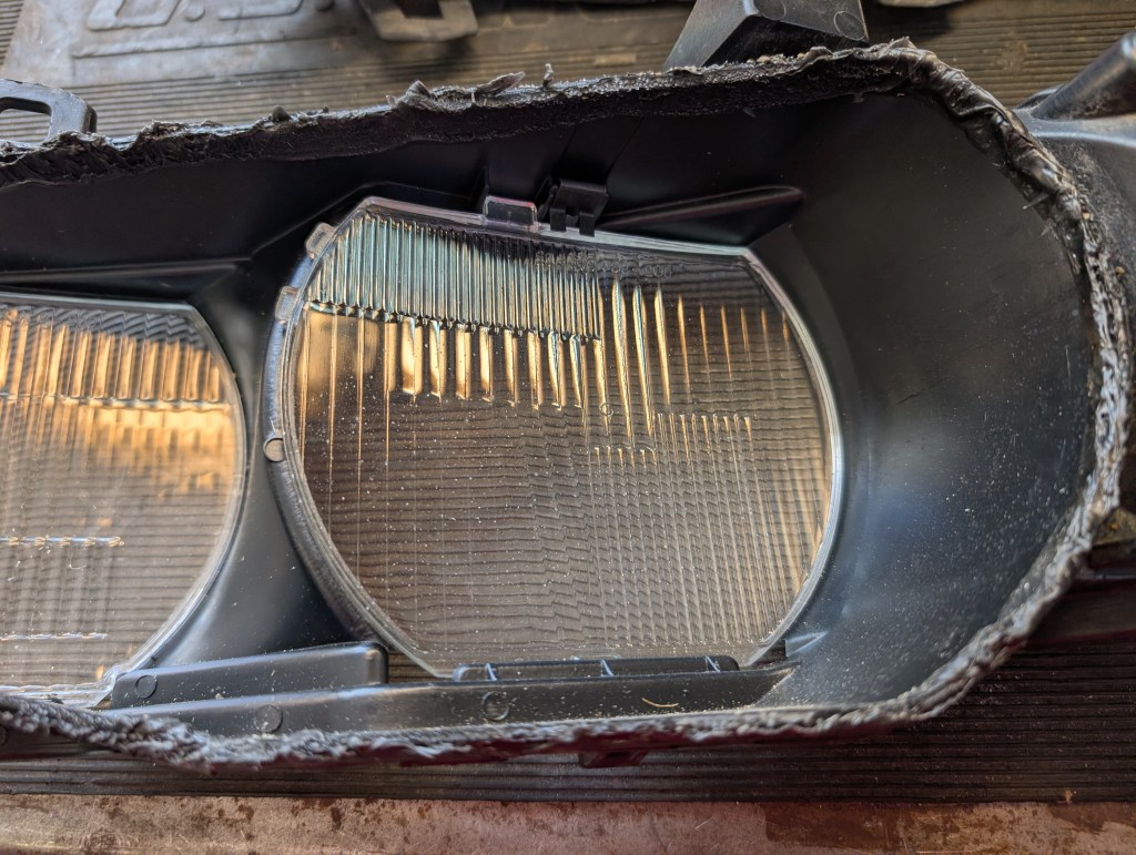
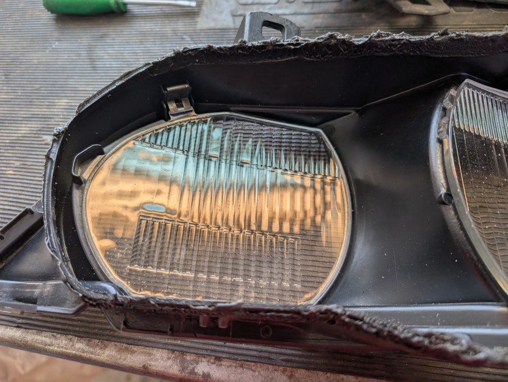
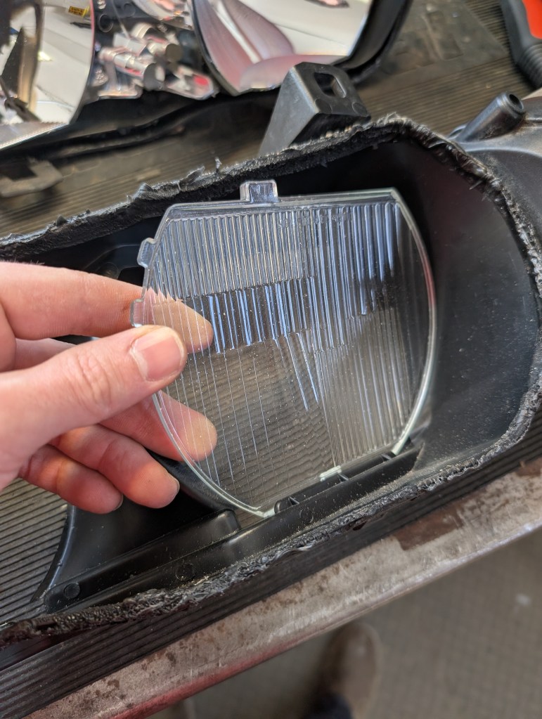
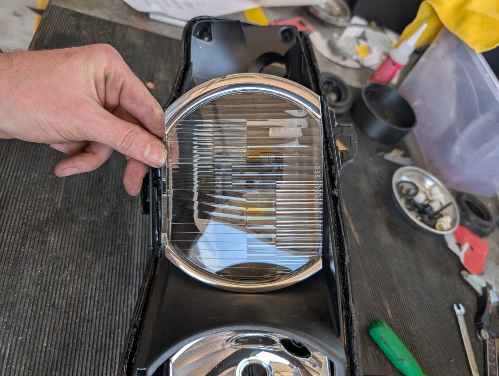
- For facelift inner lens headlights: Once the outer lens is removed, remove and store the inner both lenses in a safe place. Each lens has two “hooked” arms at the upper edge. The lower edge sandwiched between the outer lens and the middle housing which is now “free”. Rotate the lower edge in the forward direction allowing the lens to pivot on the upper edge to clear the hooks and be removed the inside lip of the middle housing.
- Contingent: If a hook happens to be broken and the pieces are recovered, a dab of the Starbond CA glue on the lens remnant side is ideal, with the hook held in the small pliers spray with the accelerator on the contacting surface and press together.
- Contingent: If a hook happens to be broken and the pieces are recovered, a dab of the Starbond CA glue on the lens remnant side is ideal, with the hook held in the small pliers spray with the accelerator on the contacting surface and press together.
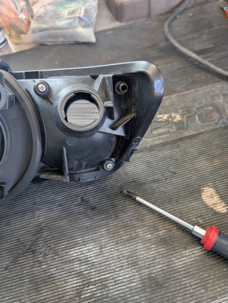
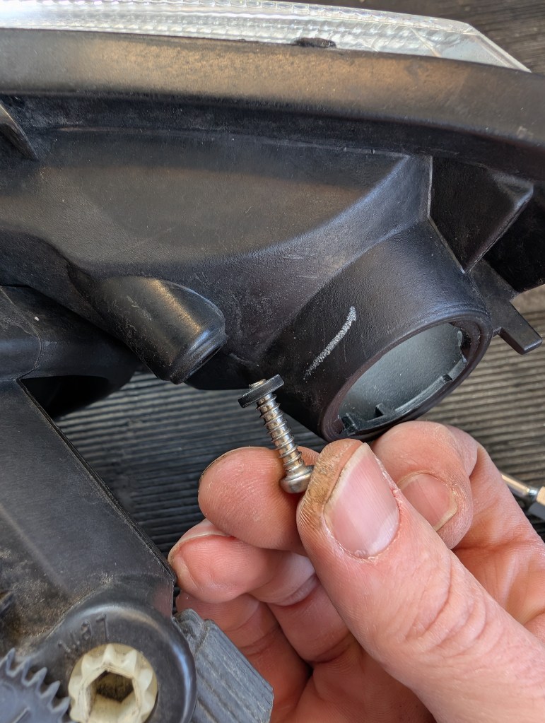
- The turn signal is not required to be removed from the middle housing but I do to ensure that its not damaged during the retrofit process. It’s held in place by two Phillips screws, remove the screws and ensure that the sealing o-ring is retained and not lost. This is also the time to swap clear/amber corners as desired. Store the turn signal and hardware in safe location for re-use at reassembly.
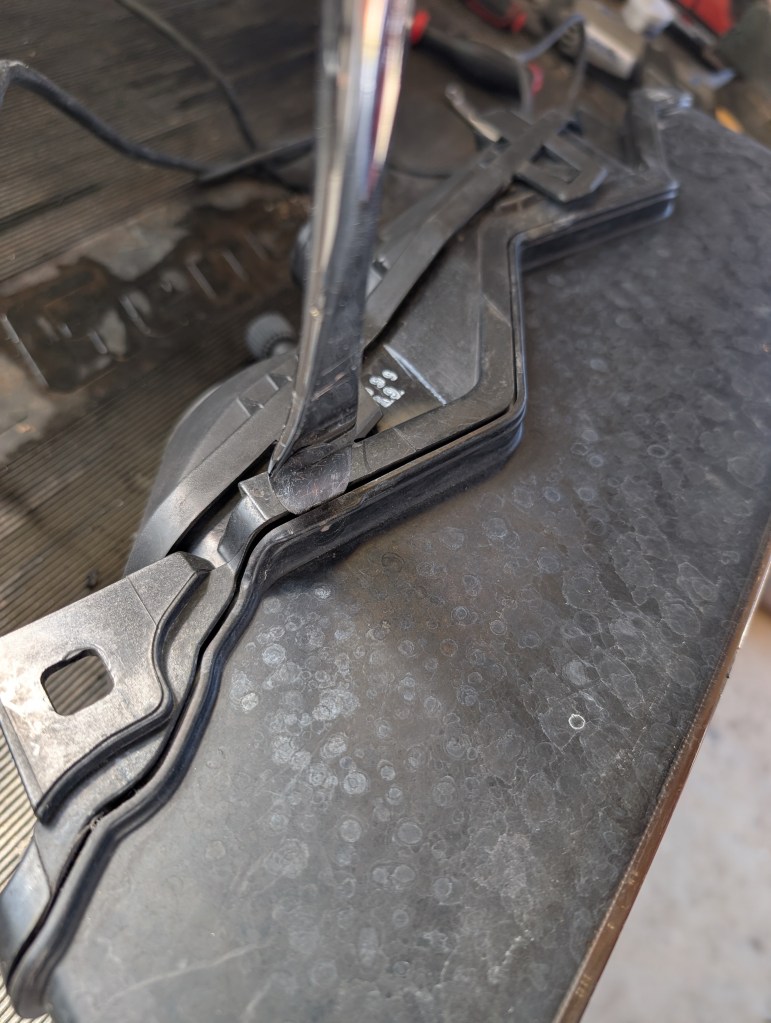
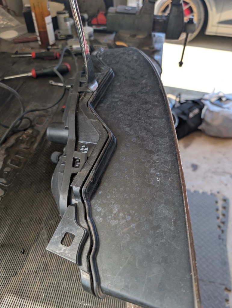
- The rear/middle housing joint is separated next in the same manner as the outer lens was in step 2) above. Avoid/Limit prying on the fourd mounting points to the car of the middle housing and the three clip tabs of the rear housing during separation. I’ve in haste applied too much pressure to these critical points and broken them. You’ll need to release the clips between the two housing when prying as well, a plastic pry tool to keep the pieces part is advised.
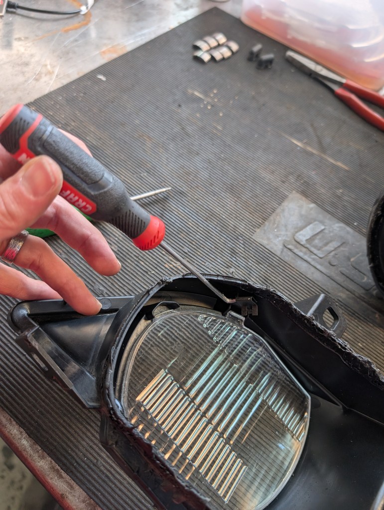
- For non-face lift models that need to remove the glass lens(es), the glass lens is attached to the inside of the middle housing with a metal retaining clip. Using a right angle pick remove the clip and the glass lens can be removed.
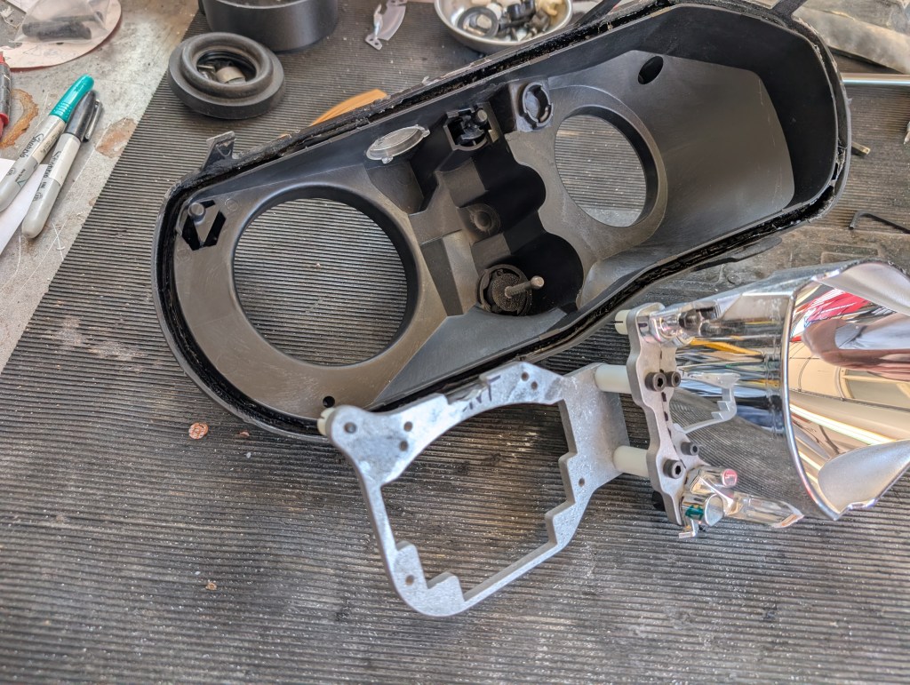
- Store the middle housing in safe location for future reuse
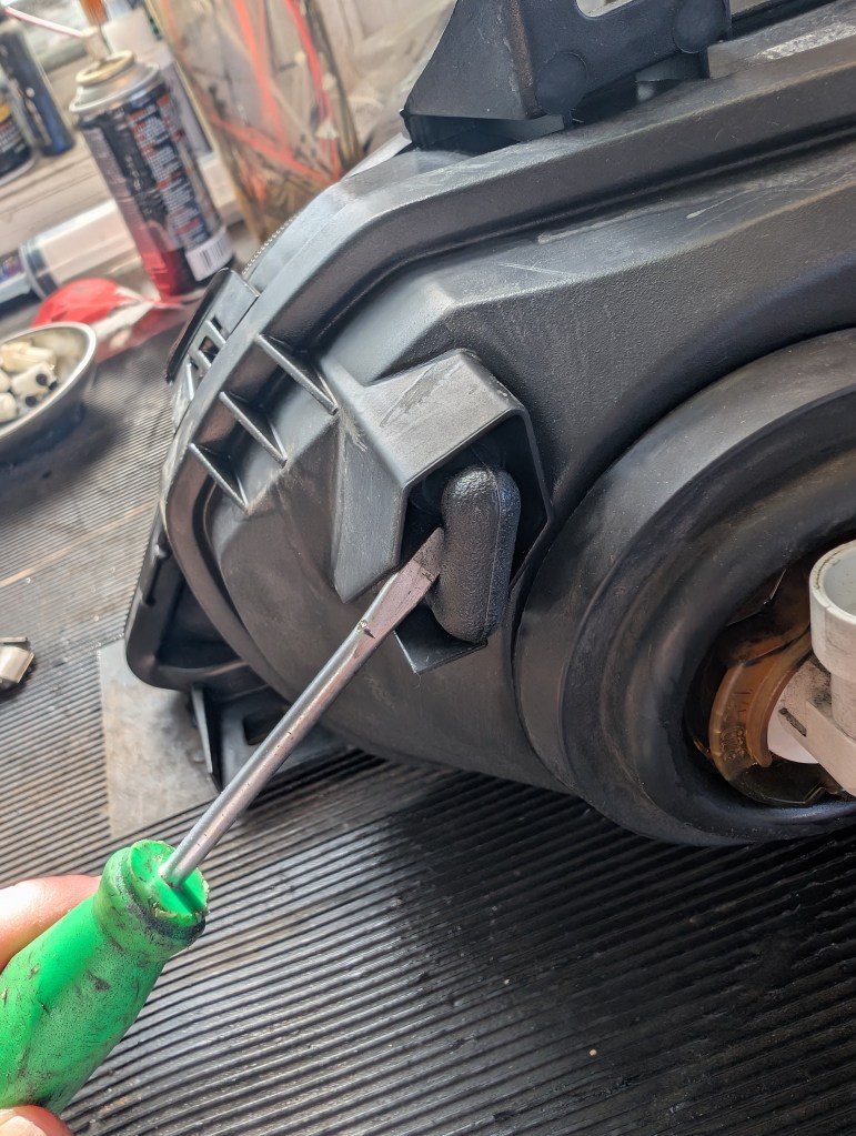
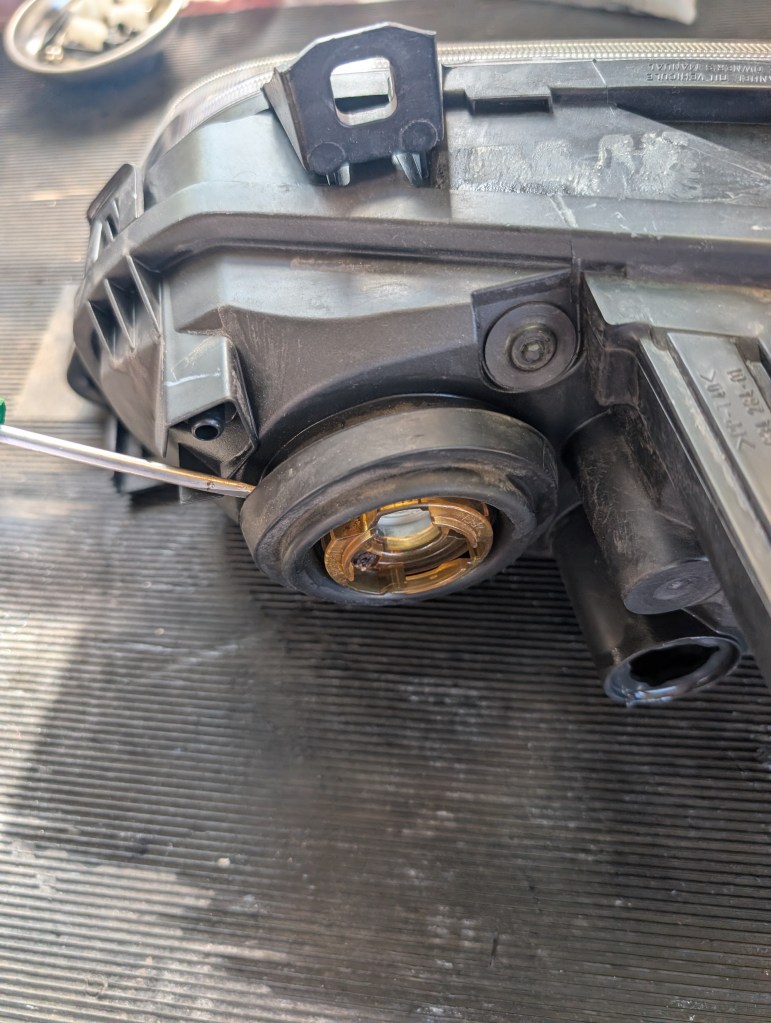
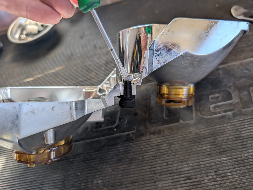
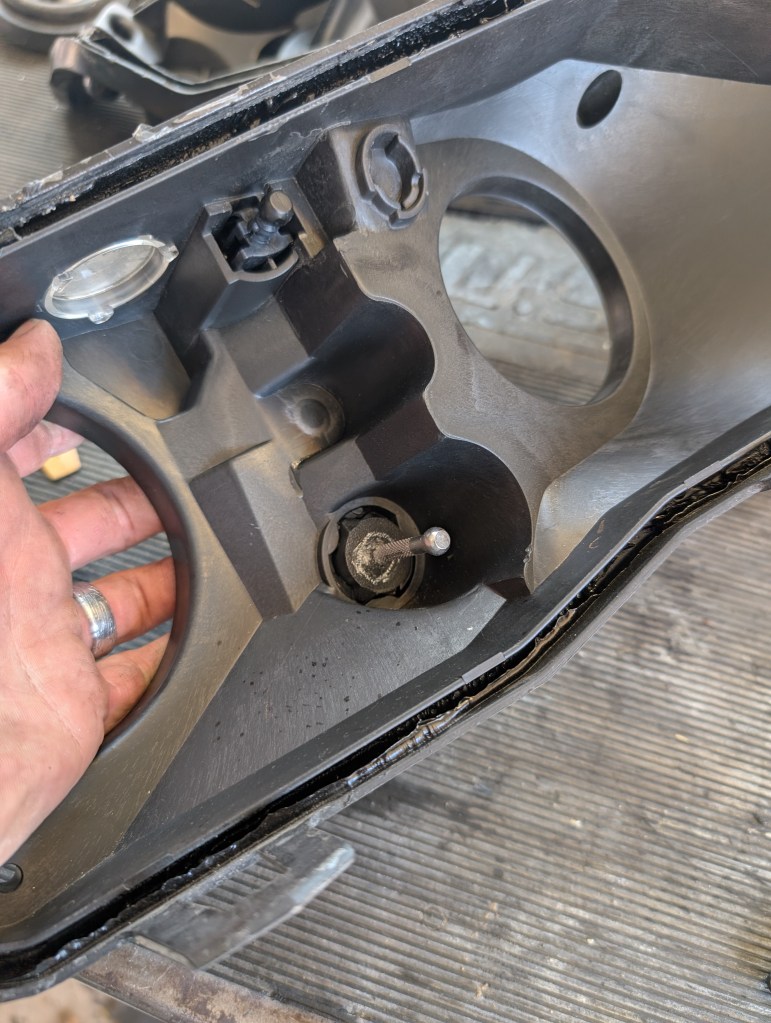
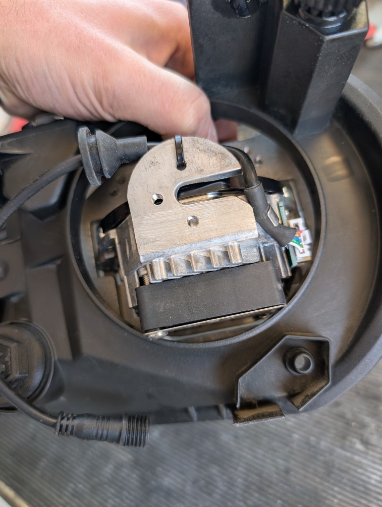
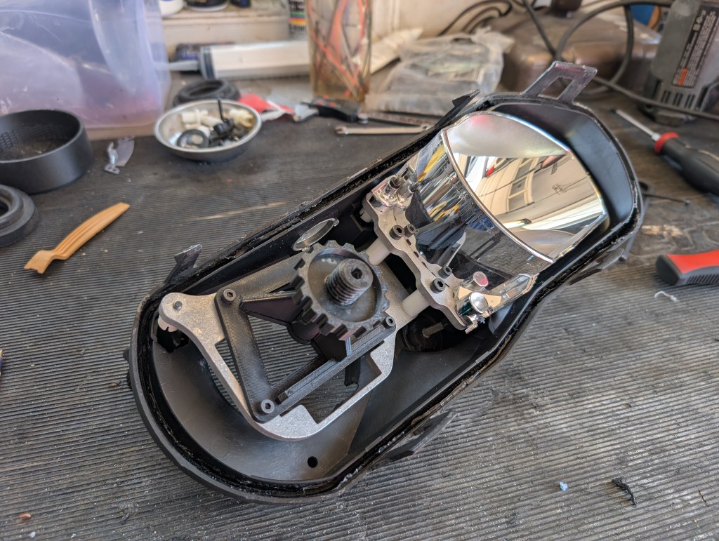
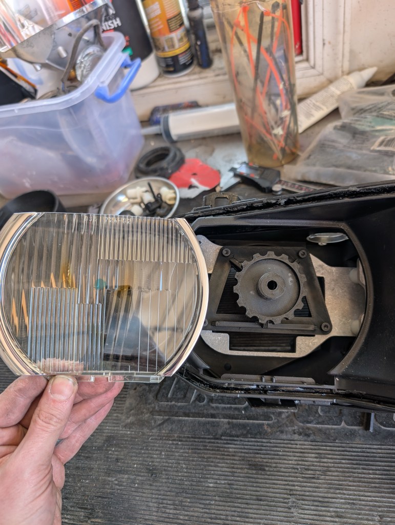
- With the remaining rear housing and bowl assembly remaining, the bowl needs to be removed from the rear housing for modifications. Using the aiming adjusters on the back of the housing (6mm allen on large black knob), position the white ball sockets attached to the bowls into a position that allows a good prying location. With a large pry tool separate the socket from the rear housing ball starting with the left/right adjuster then moving to the up/down.
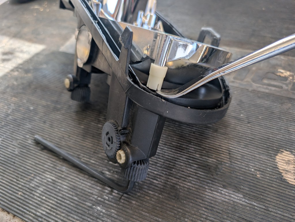
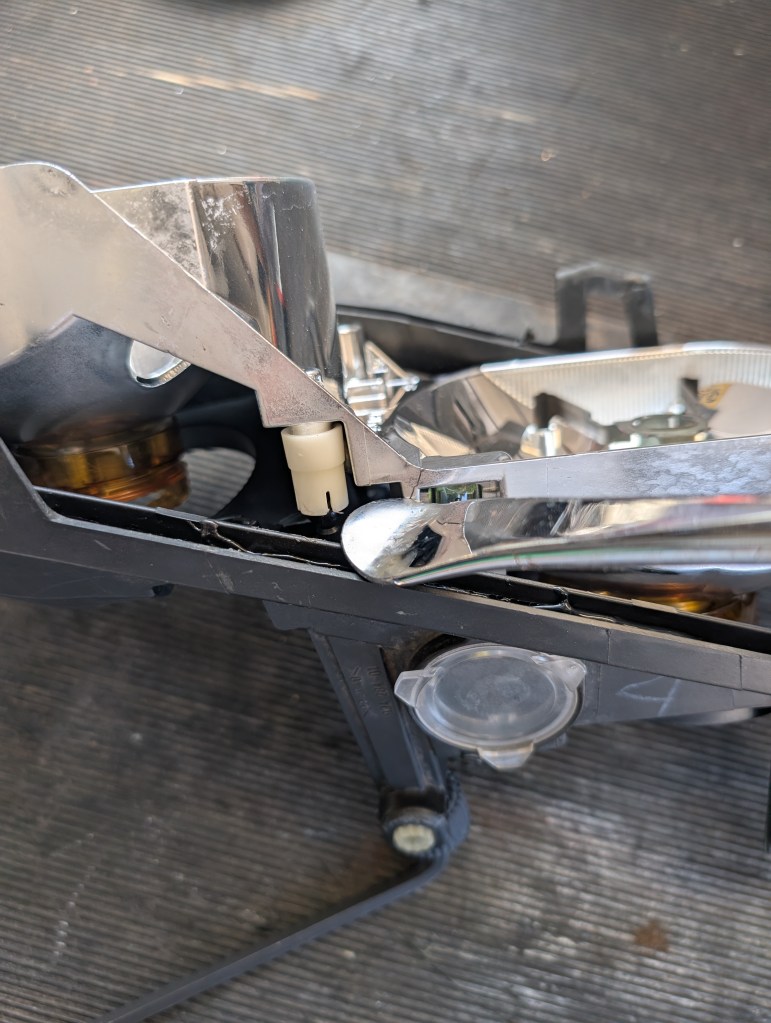
- If the fixed pivot was not previously removed in section 2 above, the fixed socket can be slid to the left/right to release the ball or the small clip can be pried off the bowl assembly and the assembly pulled off the socket. Or if it was still attached to the headlight assembly as the mount was gone, retain the knurled ball stud in safe place and perform the fixed pivot repair with it.
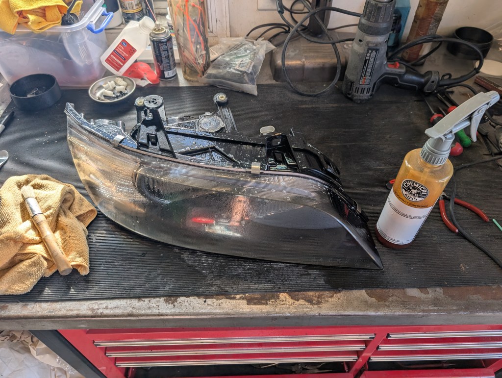
- With the rear housing disassembled, it’s a good idea to hit all the adjuster moving parts with a bit of tri-flow to refresh them. Apply a bit and run the adjusters up/down and let that sit in. Clean up any residuals after it dries.
- Now is the best time to give every piece a good cleaning for any hard to reach areas as well.
Headlight parts modification begins:
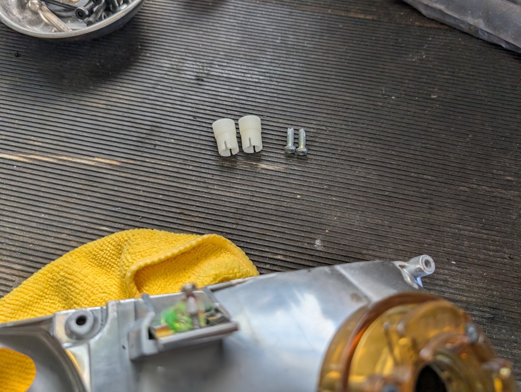
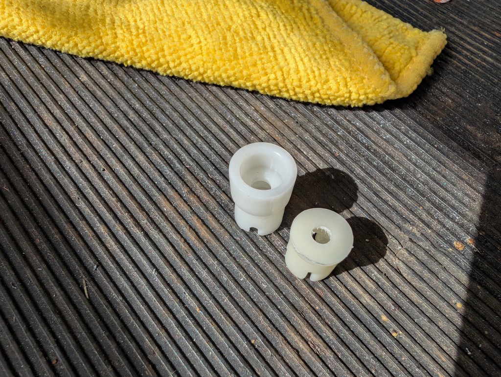
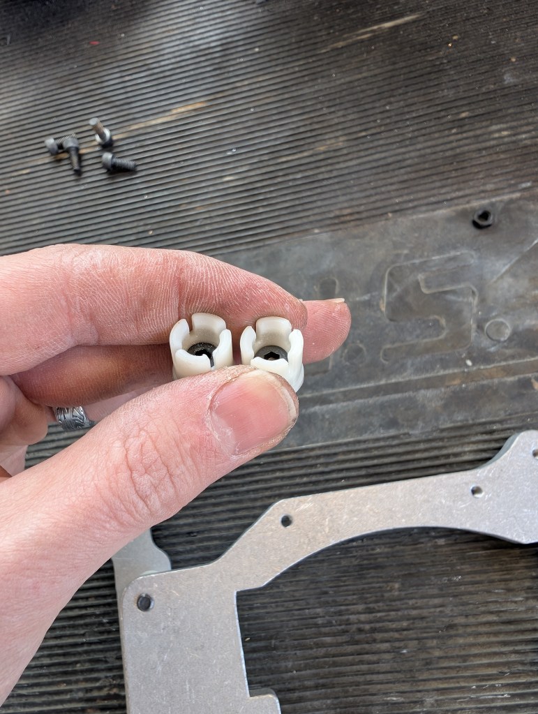
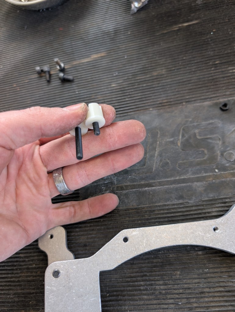
- The three ball sockets are re-used in conjunction with the retrofit kit. The lower fixed socket just needs to be removed and retained for future assembly, there are NO modifications to the fixed socket. The left/right and up/down socket need to be removed and modified.
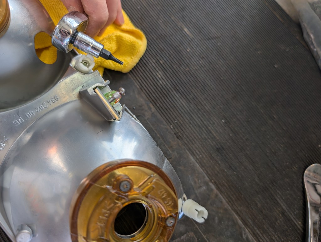
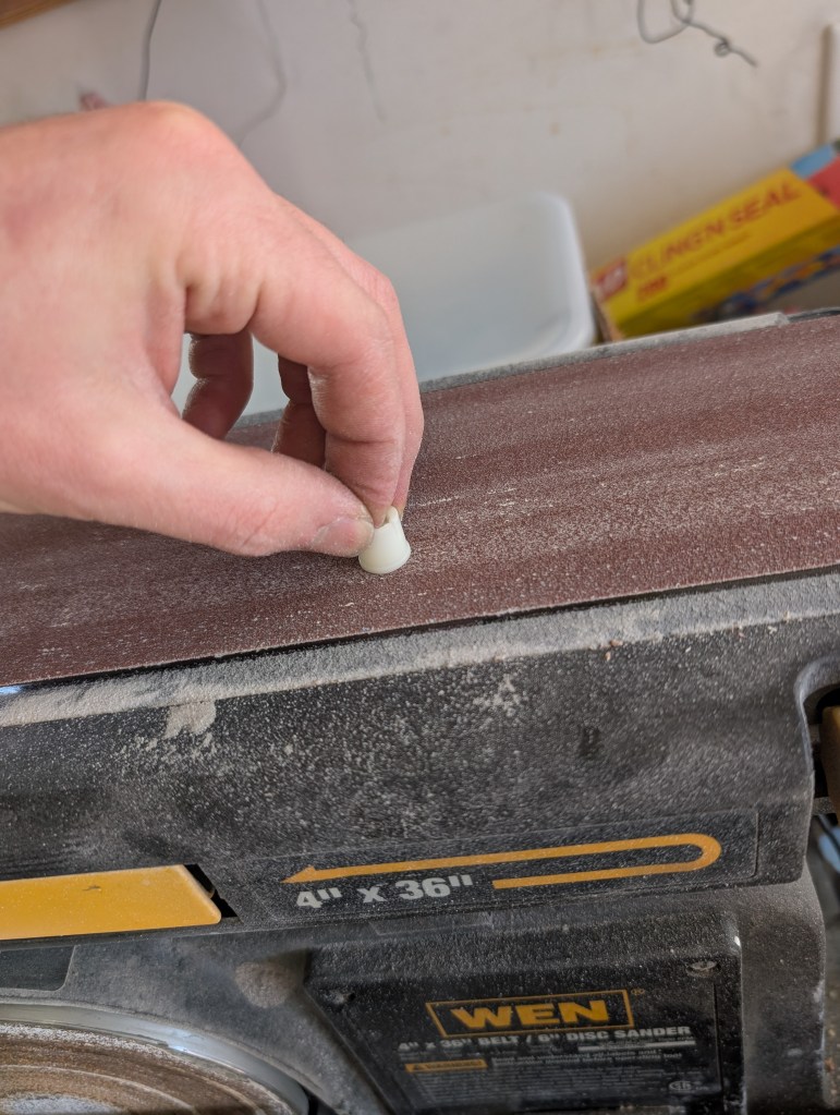
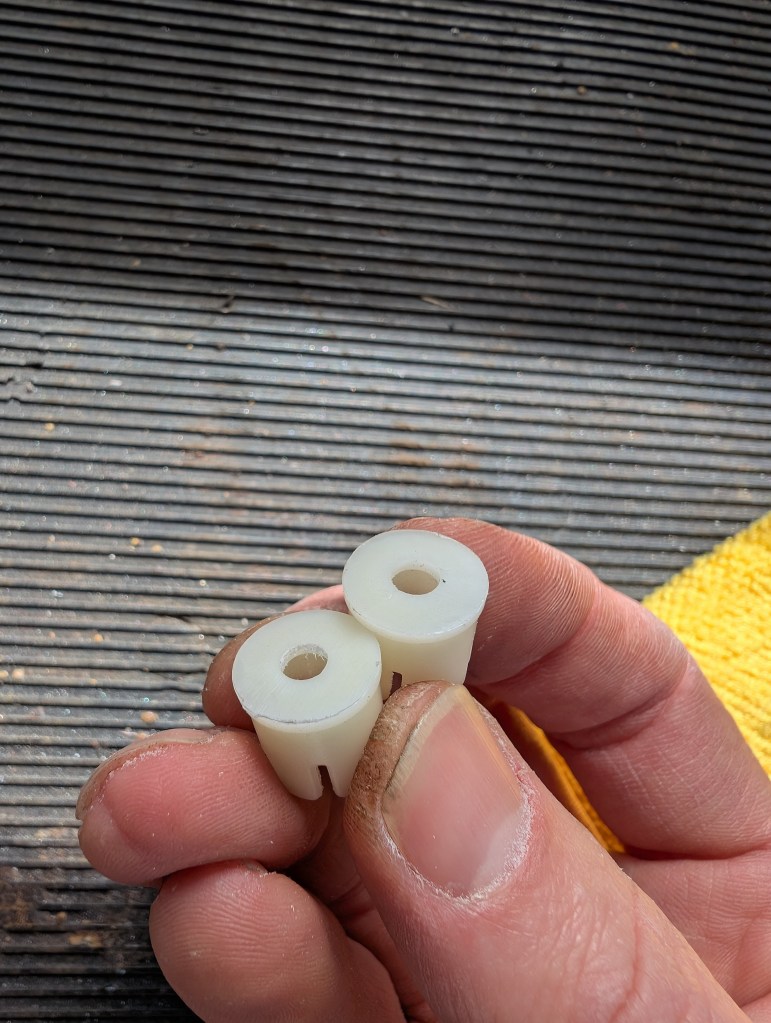
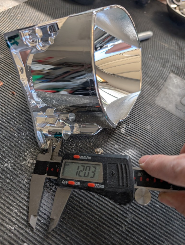
- The aiming sockets are removed with a T10 torx bit and the screw can be discarded. The aiming sockets start lift at around 18mm in height and will be cut down to 12mm when done. I use my belt sander for this but you could also use a Dremel and some sand paper if needed. The ~6mm of removed material will be from the FORWARD face of the socket that is in contact with the bowl assembly/retrofit bracket. Essentially there is a “cup” in the original socket that is removed and made to be a flush mount face face. The socket face should be left as-is.
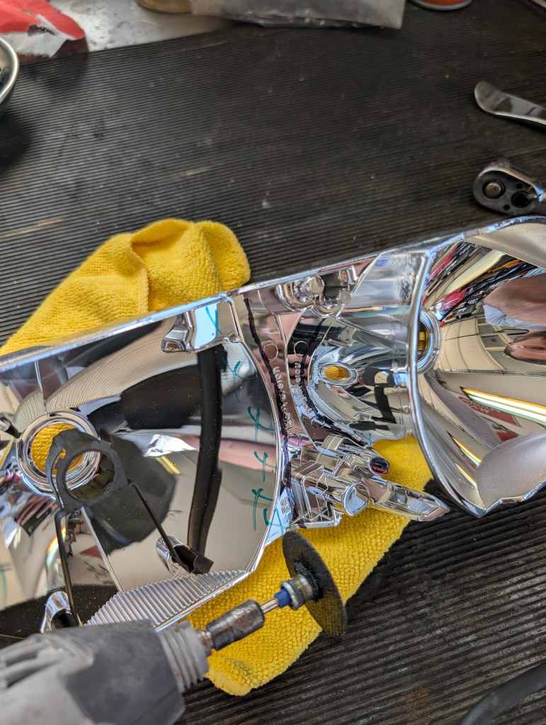
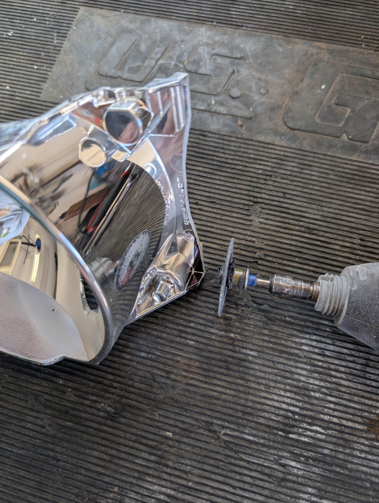
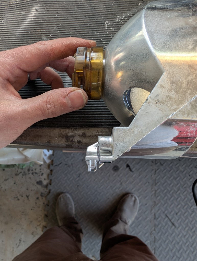
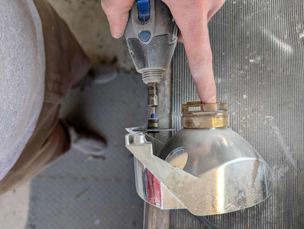
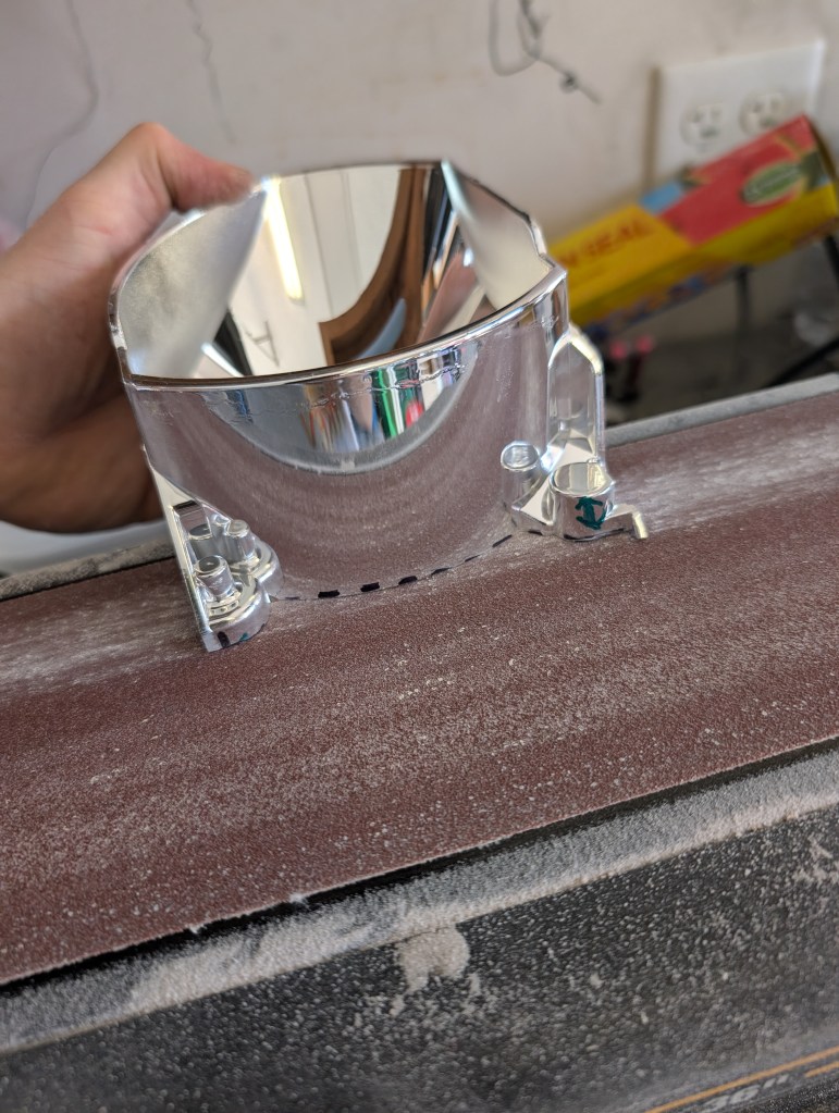
- The bowl assembly needs to be generally separated and the high beam bowl cut precisely to reassemble with the retrofit bracket. The material of the bowl assembly makes a very fine white dust. It is highly suggested to wear eye and respiratory PPE for the cutting process in a well ventilated area.
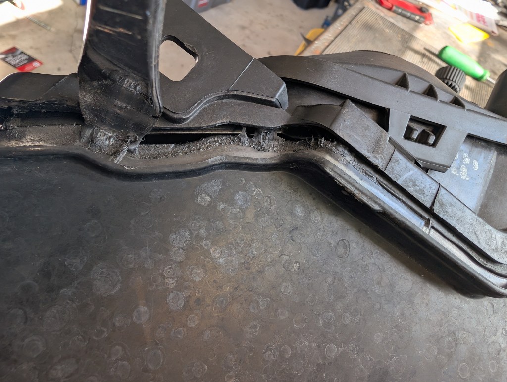
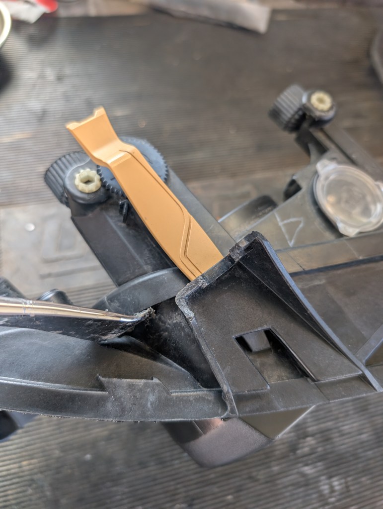
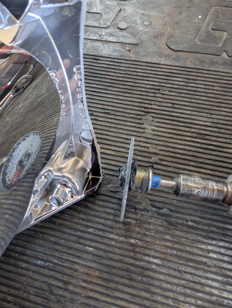
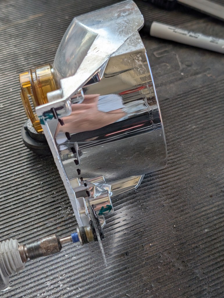
- Separate the two with a general cut to remove the low beam bowl from the high beam bowl. Be aware of your Dremel blade and the bubble level but otherwise a general cut, the blade cutting in the FWD/AFT orientation, as pictured below, to get the two pieces apart and material removed close to the two socket mounts.
- The high beam bowl needs to be cut to the proper depth to allow use of the retrofit bracket and the original fixed socket/clip.
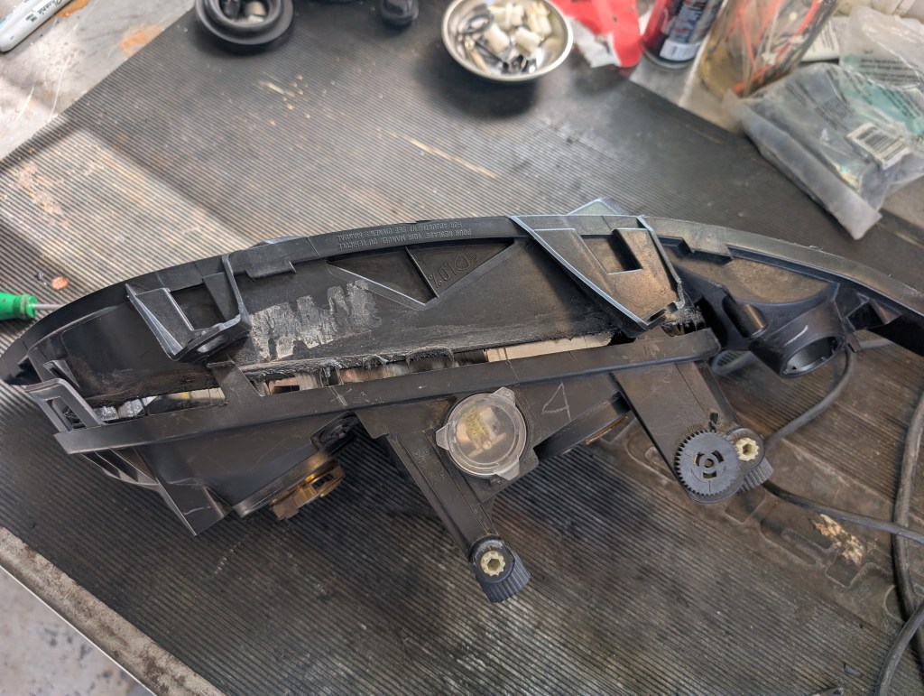
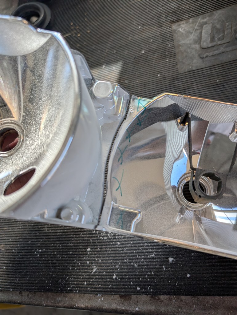
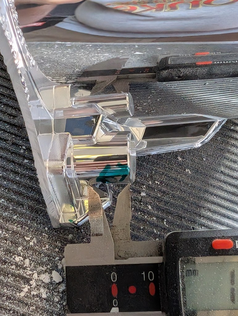
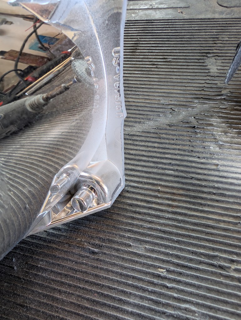
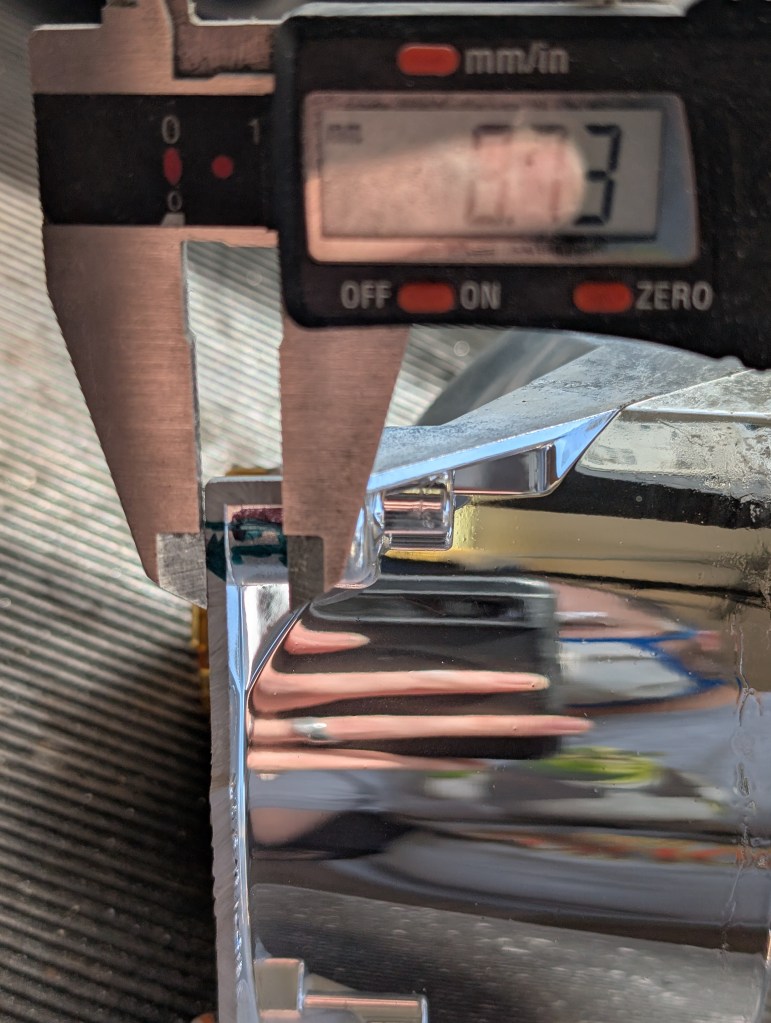
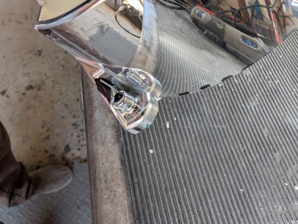
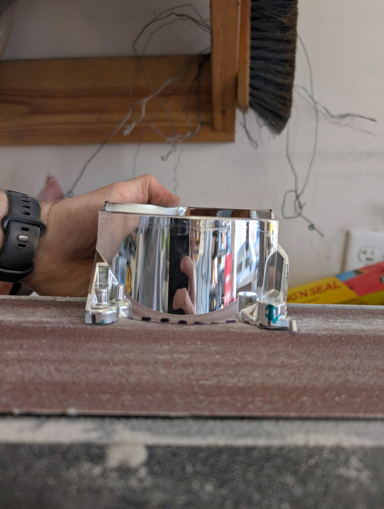
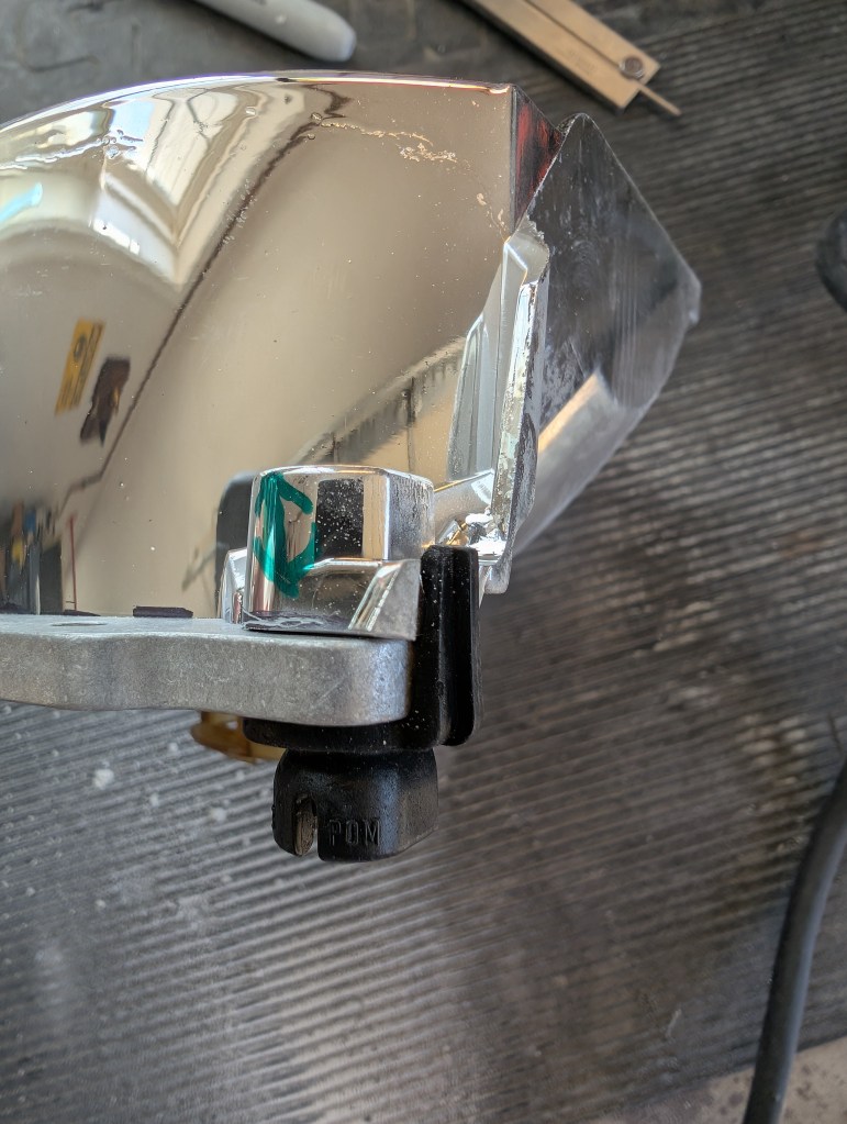
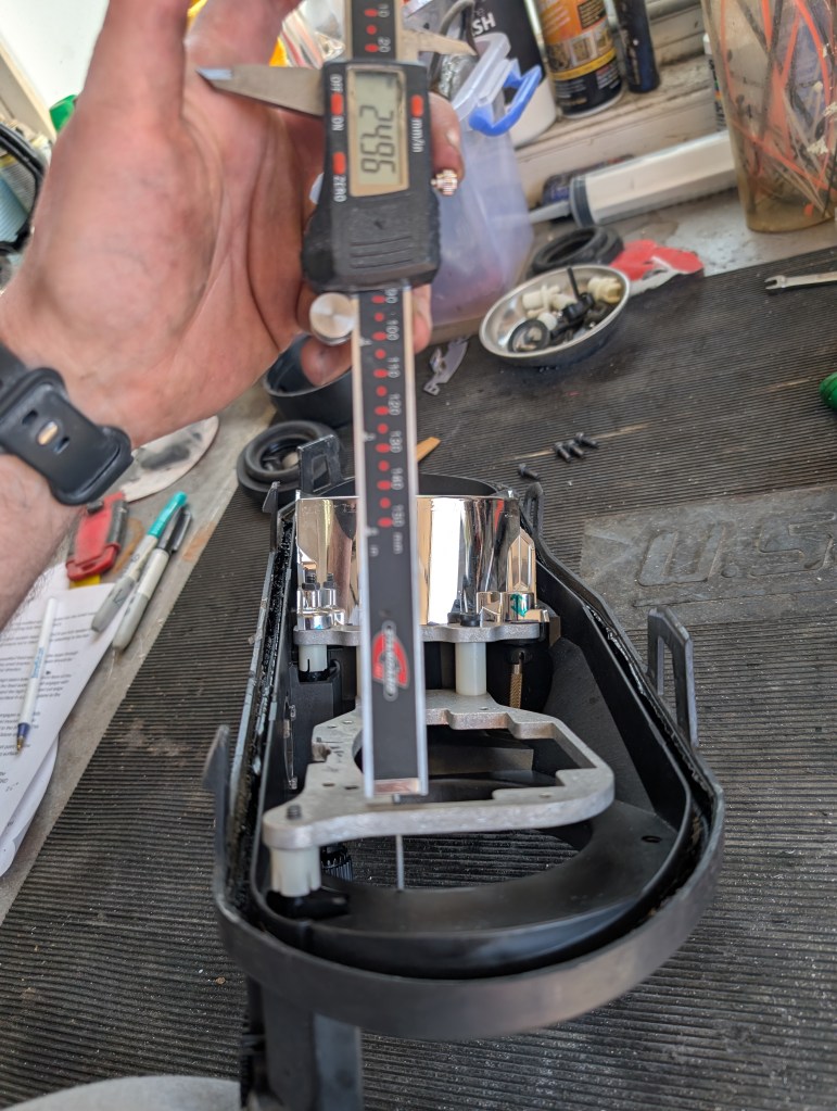
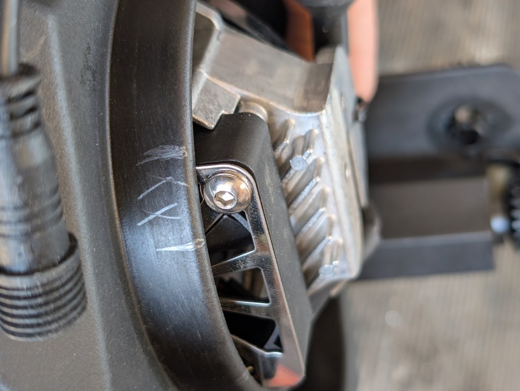
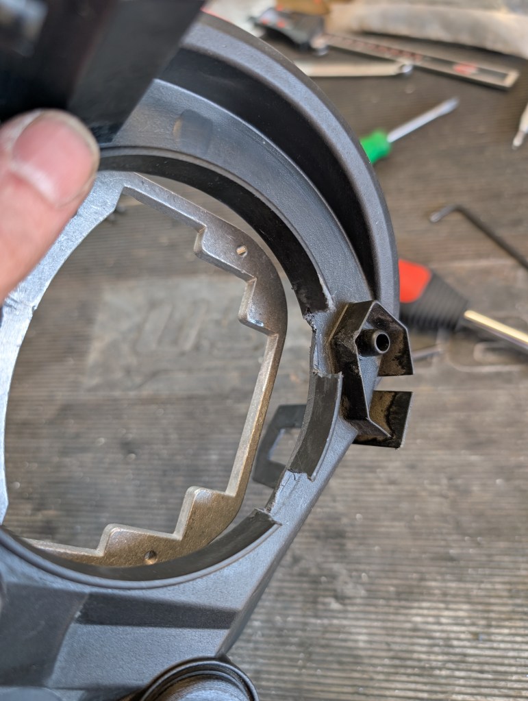
- For the lower fixed socket location, with the calipers locked to ~12mm from the FWD face of the high beam bowl attachment point (pictured below), scratch the chrome to mark the cut location. Note: It is better to leave this dimension larger if you are not confident in your measurement as it can be sanded down later during test fitting
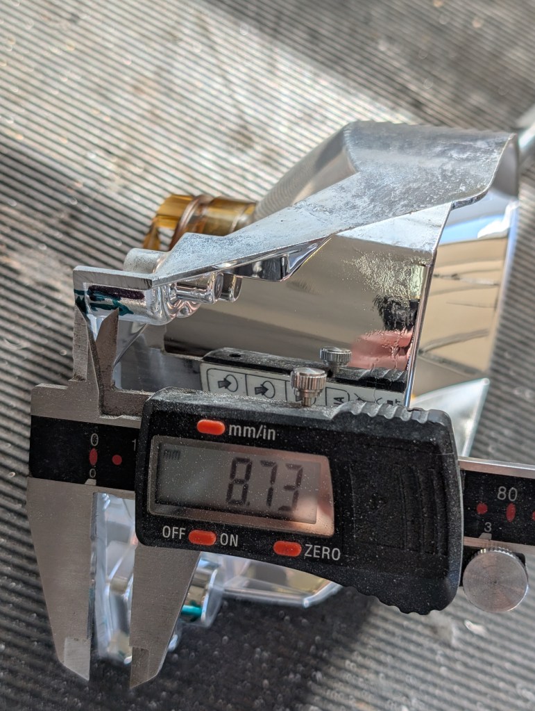
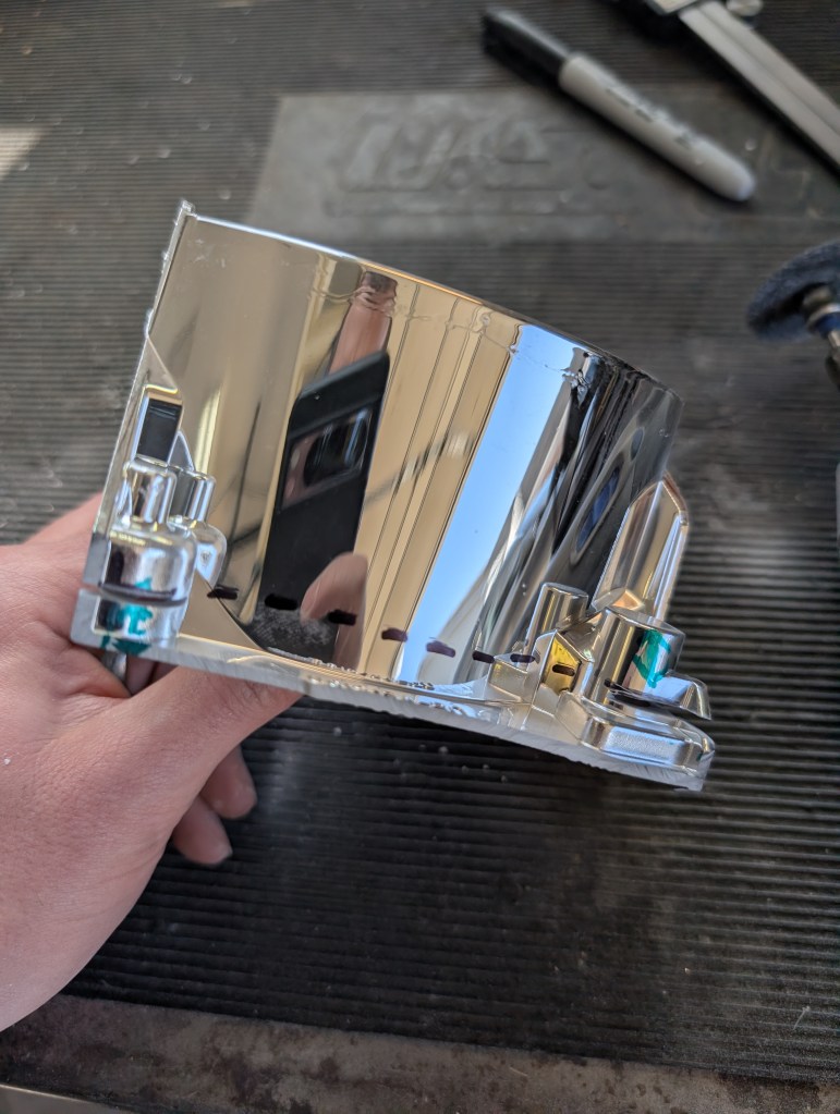
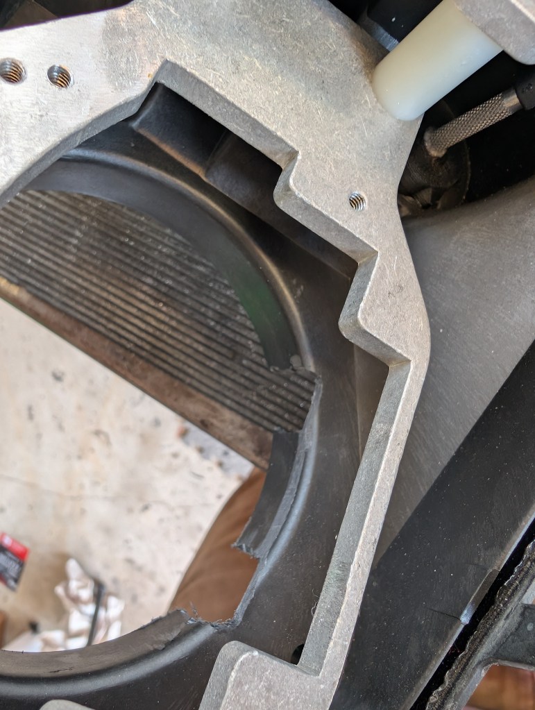
- For the up/down socket location, remove any remains of the low beam material to be flush with the large shoulder area. With the calipers locked to ~8.75mm from the AFT face of the high beam bowl material, scratch the chrome to mark the cut location. Note: It is better to leave this dimension shorter (less the same amount from the measurement in step 1 above) if you are not confident in your measurement as it can be sanded down later during test fitting
- With the Dremel blade cutting in the left/right orientation in parallel plane to the FWD edge of the high beam bowl, make initial local cuts with the blade on the AFT side of the two marks from above.
- After the two initial cuts, I position the bowl in a way that I can look down between these two initial cuts to align the connecting cut keeping the cut as straight and square as possible cut off the remaining unneeded material.
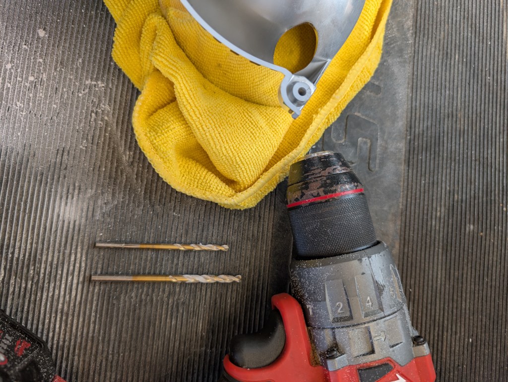
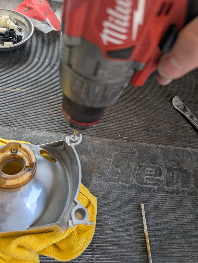
- The up/down socket in the high beam bowl needs to be made into a through hole and enlarged. Using a 9/64” bit to make the pilot through hole, followed by the 11/64” to allow the 4mm bolt to pass through during assembly. The horizontal rib above the FWD face of the new through hole will need to be cut away to allow installation of the retaining nut with a Dremel disc.
Retrofit Bracket assembly:
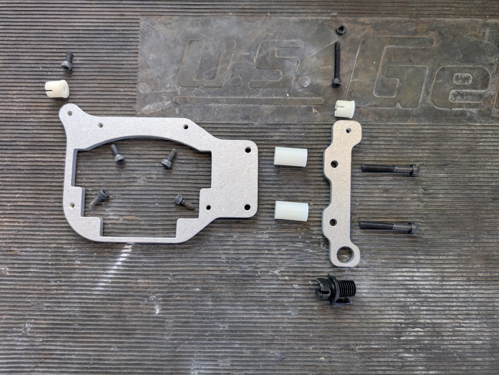
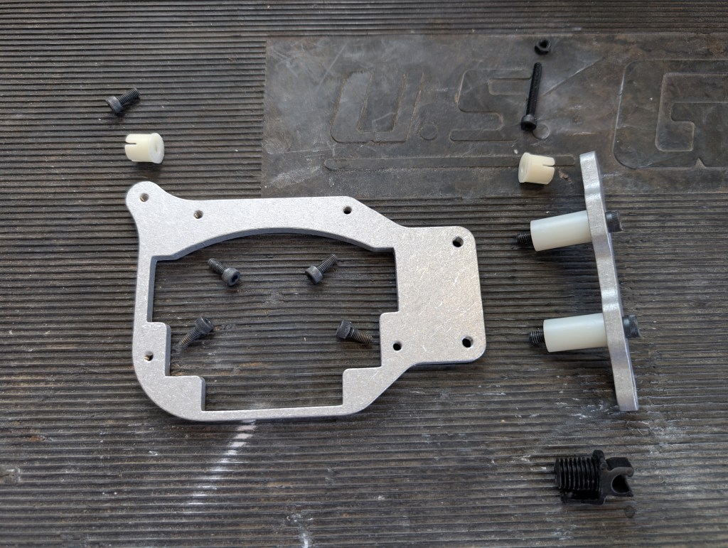
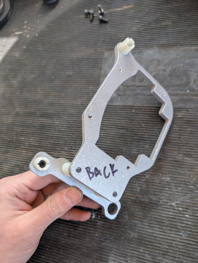
The DBG retrofit brackets are identical and just assembled in mirrored orientation for their respective side. For a right hand side headlight:
- With the small metal bracket on your work surface, orient the two middle 5mm holes to the left with the large through hole closest to you and the small threaded hole away from you.
Passenger (RH) side layout:
Driver (LH) side layout:
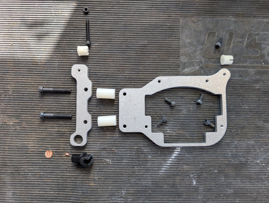
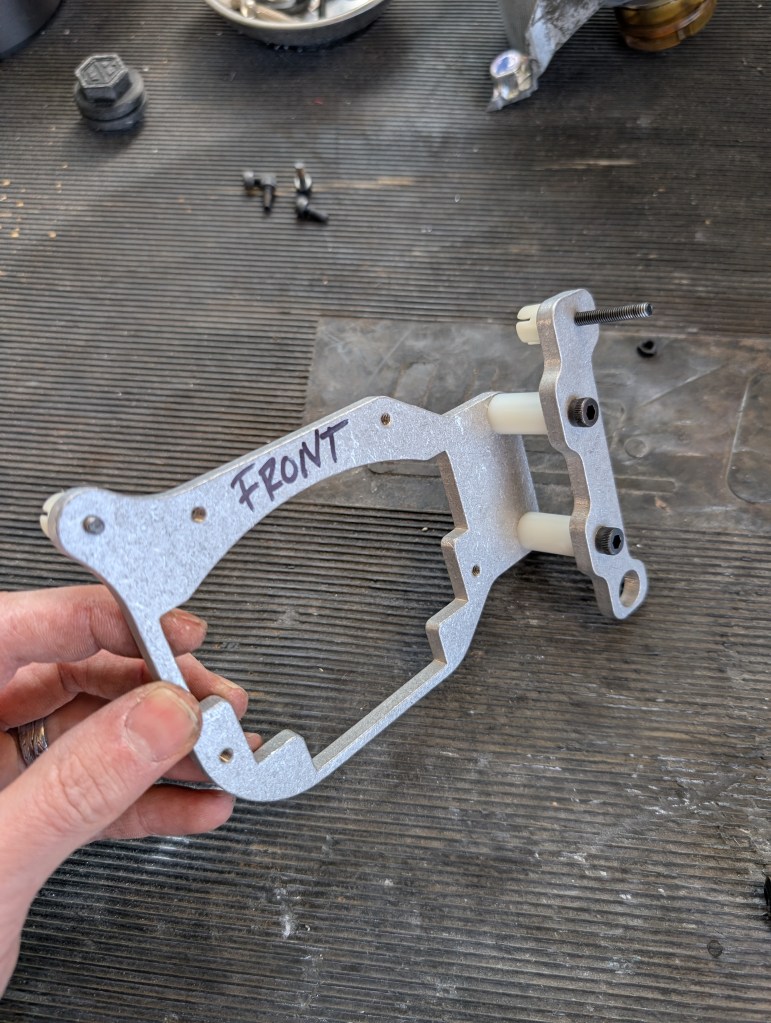
- Insert the two partially thread 5mm socket headed cap screw (SHCS) through the holes and slide the nylon spacers over the back. Install the two 5mm bolts into the larger metal bracket with a 4mm allen wrench. The larger metal bracket has the threaded “ear” which should be away from you on the left when being assembled. This is the “front”.
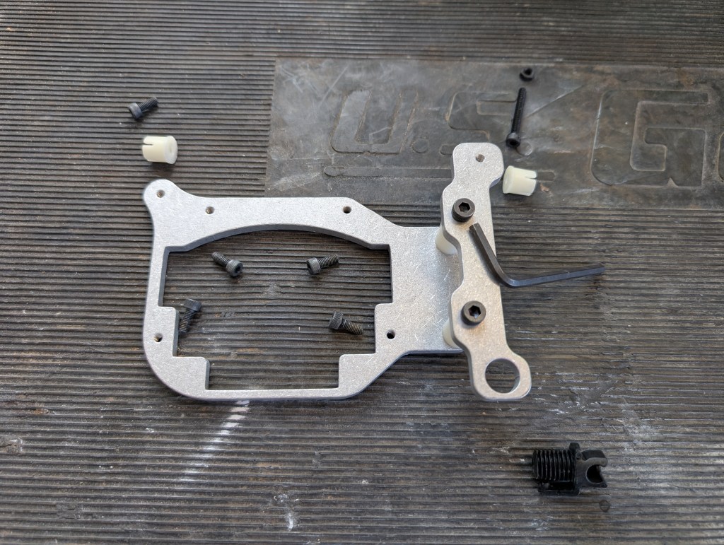
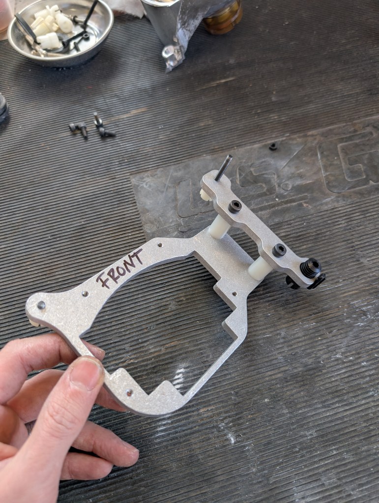
- Flip the assembly over to the back so that the large metal bracket ear is on the right and install the modified left/right socket using one of the short 4mm SHCS through with a 3mm allen.
- Install the modified up/down socket into the small metal bracket using the long fully threaded 4mm SHCS with a 3mm allen.
- Ensure both sockets respective SHCS are fully seated into their sockets to ensure not to interfere when attaching to the ball mounts.
- Insert the unmodified fixed socket into the large through hole in the bottom of the small bracket. All sockets should be installed in the AFT (back) direction.
- Test fit the modified high beam bowl to the front face of the small metal bracket to ensure the fixed socket clip will engage with its original corner. As needed, sand the high beam bowl cut edge to dial this in keeping the sanding surface in a parallel plane to the front edge of the high beam bowl.
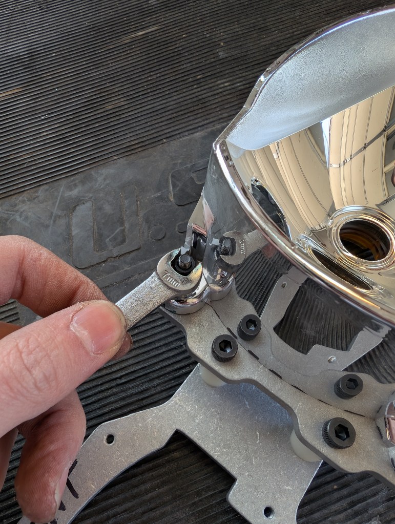
- Once the lower fixed socket clip engages successfully, install the 4mm nut over the up/down socket mounting bolt to attach the upper point of the high beam bowl to the bracket using a 7mm wrench. This unit is referenced as the “bracket assembly” in future steps.
Retrofit Rear Headlight assembly:
- If previously removed, reinstall the fixed pivot point into the rear housing using a light coat of alcohol on the o-ring surface during assembly.
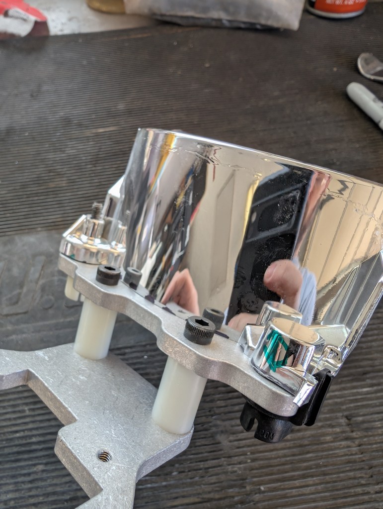
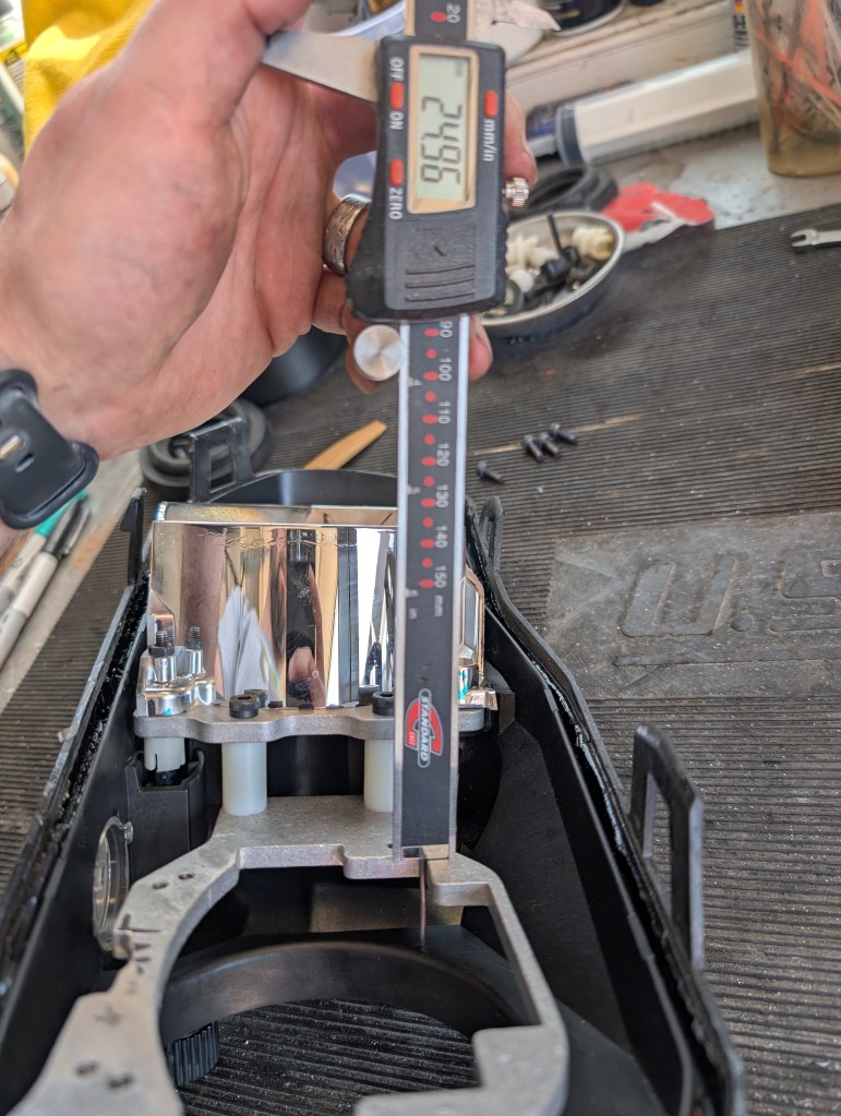
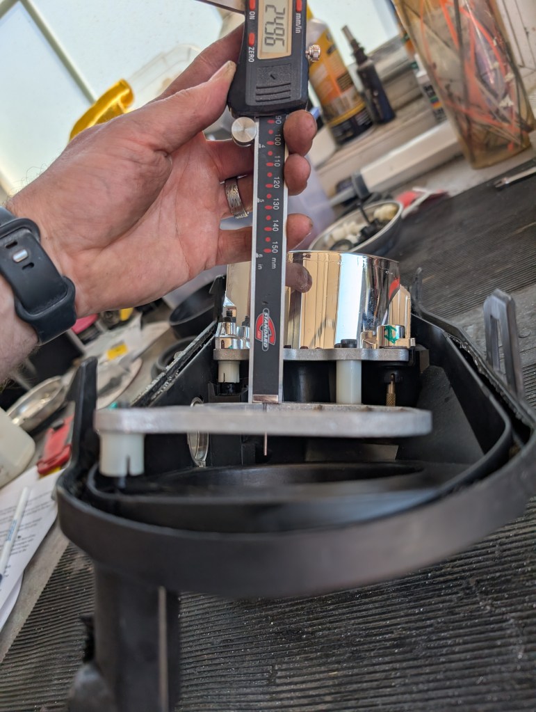
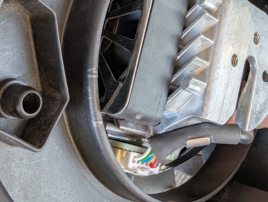
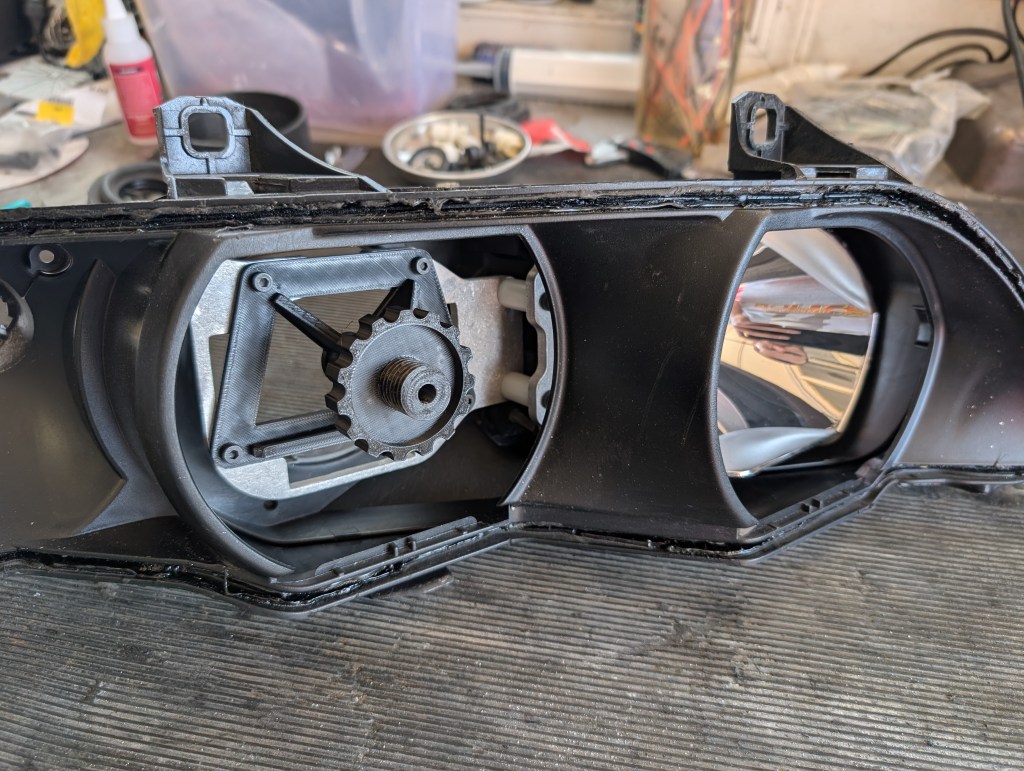
- Clip the bracket assembly into the rear housing. Using the caliper, measure the depth of the large bracket to the inside FWD face of the rear housing, it should be approximately 25-26.5 mm’s. Adjust the up/down and left right (6mm allen on large black knob), such that all three locations are equal in depth to the FWD face of the rear housing. Photos below show how the three spots will likely be very different, ensure they all match the 25-26.5 measured at the fixed pivot spot.
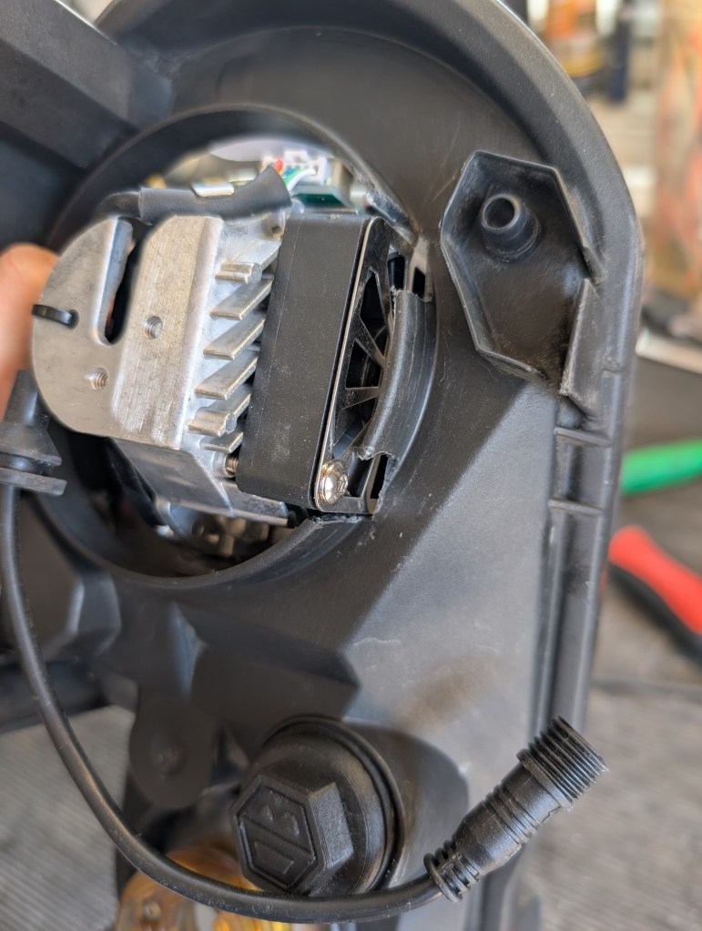
- The rear housing needs to be clearance for the LED cooling fans. Hold the BiLED into its mount mounting position and mark with a pencil the lip of the rear housing low beam that needs to be removed. Remove the BiLED and store in a safe location.
- I use a finger sander to remove this material and a file to clean up the edges. A Dremel or other tooling could be substituted if a finger sander is not available. Note: Minimum cuts should be completely covered by the DBG weather cover. If clearancing is excessive, some gaps could exist but would likely be hidden from normal viewing when installed by the weather cover.
Retrofit Lens Cutting:
- Cutting of the inner outboard lens: To ensure the best alignment reassembly of the middle and rear housings for drilling in place is highly suggested. If using an DBG inner shroud this will require re-disassembly of the housings for final installation. Reattachment is a lot like disassembly with a cycle of general heating of the full perimeter of each housing and then focused heating for any spots that are stubborn to get them fully seated and clipped together.
Caution: when handling the outboard lens be aware of the two upper attachment arms. They are prone to breaking if handled roughly and would need reattachment with the CA glue to hopefully be useable.
- Attach the drill guide in place of the BiLED using the four each 4mm SHCS with a 3mm allen. Remove one of the two lens support fasteners and set aside. (Disregard the notch at the top of my bracket, this is for a “demon eye” installation that is outside the scope of this DIY). I goofed and didnt catch it but the two lens fasteners are cupped, the photos below show it installed “upside down” and needing to be flipped over. The photos down in step 6 show it correctly flipped.
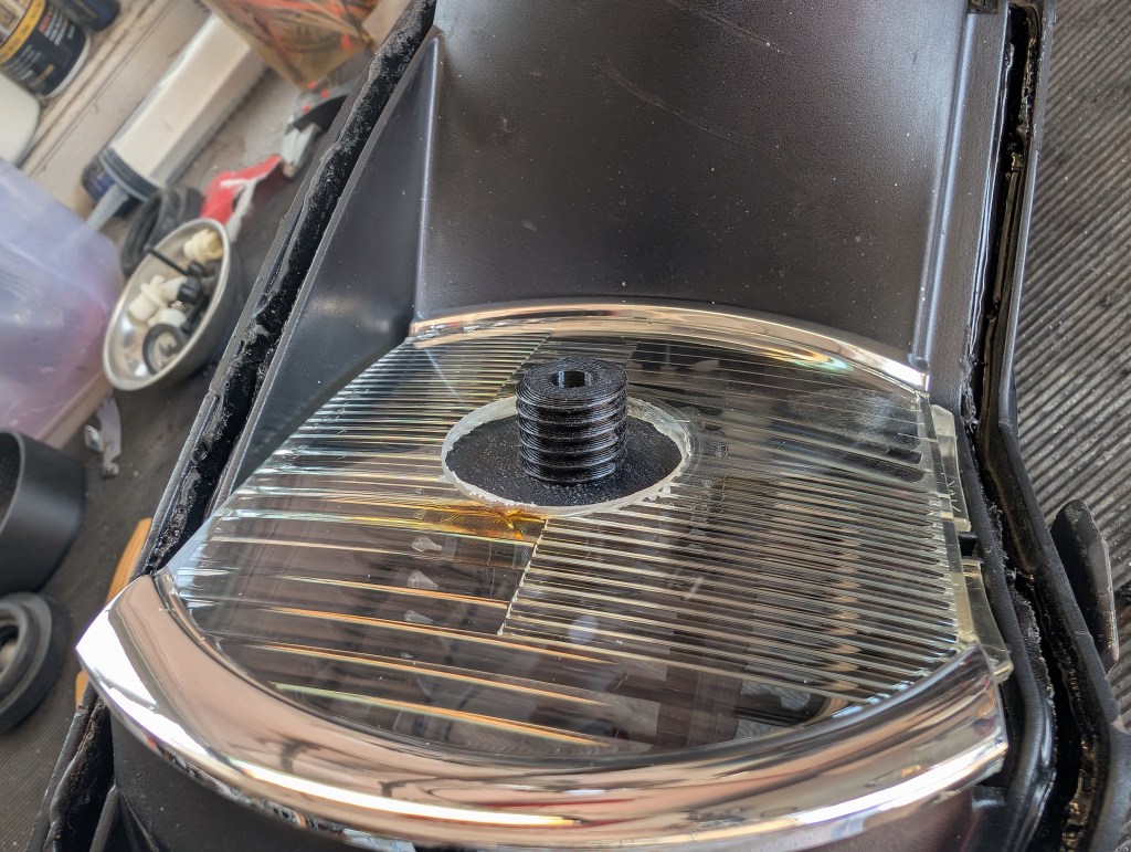
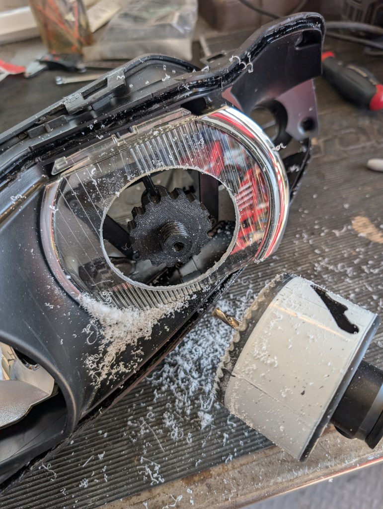
- Roughly position the outboard lens over the drill guide where it would install and mark the center hole. This does not have to be perfect, just in the ball park.
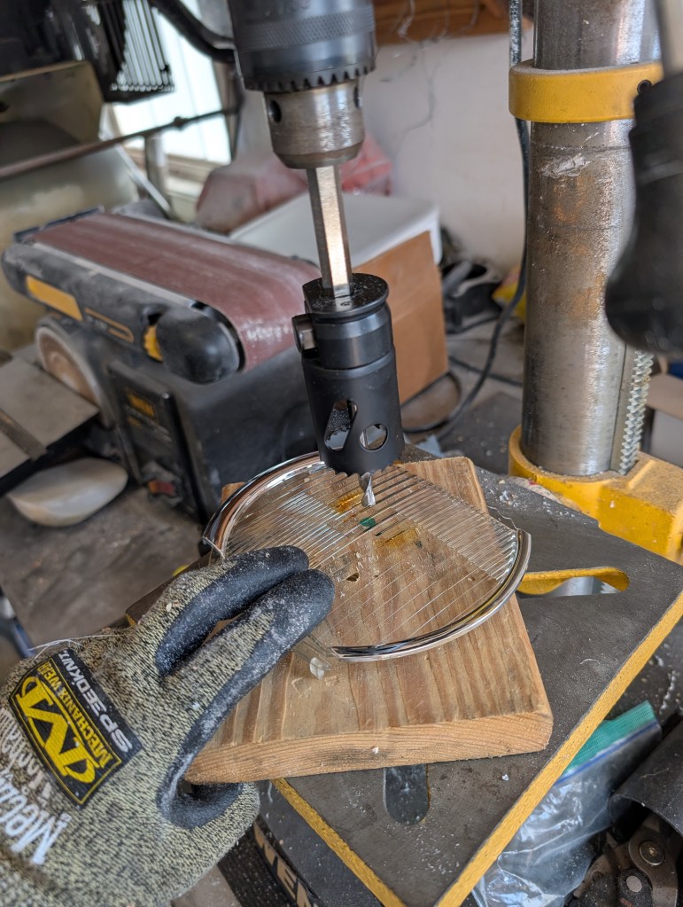
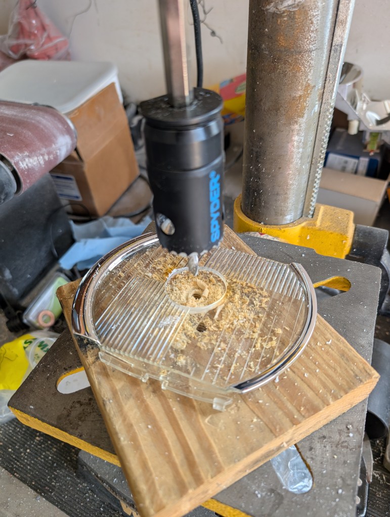
- I use my drill press for the initial hole cut but could be done with a handheld drill. Using a 1.5” hole saw, make a hole on the mark made on step 2 above ensuring the lens is supported to the maximum extent practical and the hooks are positioned to not be damaged. Slow, even pressure is highly suggested, letting the teeth do the cutting and not melting the plastic. Clear any debris as needed with compressed air, avoiding direct contact with the chromed surfaces.
- With the 1.5” pilot hole, temporarily reinstall the outboard lens. Adjust the height of the second lens support fastener such that it just contacts the back side of the lens as if fully installed (the upper hooks in position and the lower edge resting on the middle housing). Reinstall the previously removed support fastener on the FWD side , cup side out, of the lens and tighten into place ensuring to enough torque to squeeze the outboard lens but ensure its not transferred into the lens against the housing which could cause hook breakage.
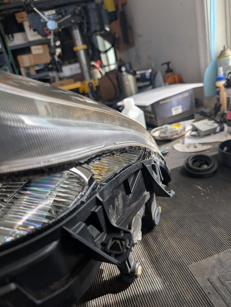
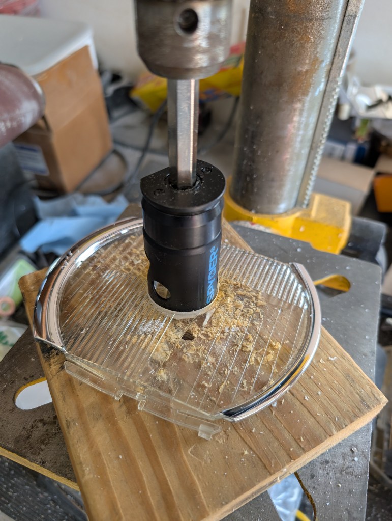
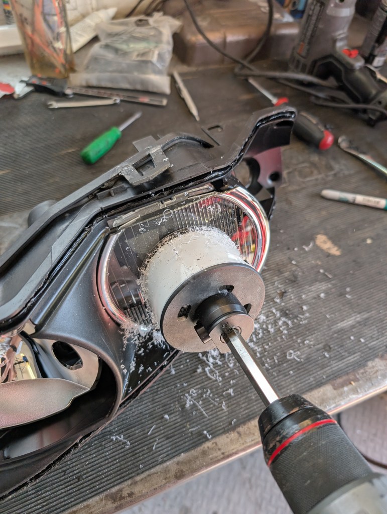
- Now comes the fun part of drilling a massive 3.25” hole in the not easily replaceable outboard lens. With a hand drill and the 3.25” hole saw with ¼” pilot drill bit. Cut the outboard lens in place. Again applying slow even pressure to “cut” the lens in lieu of melting it.
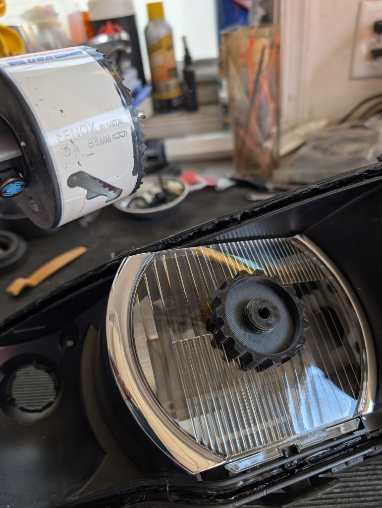
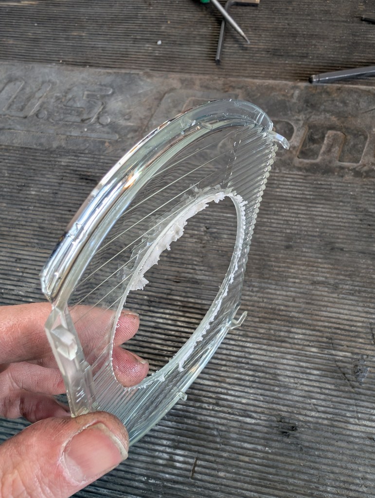
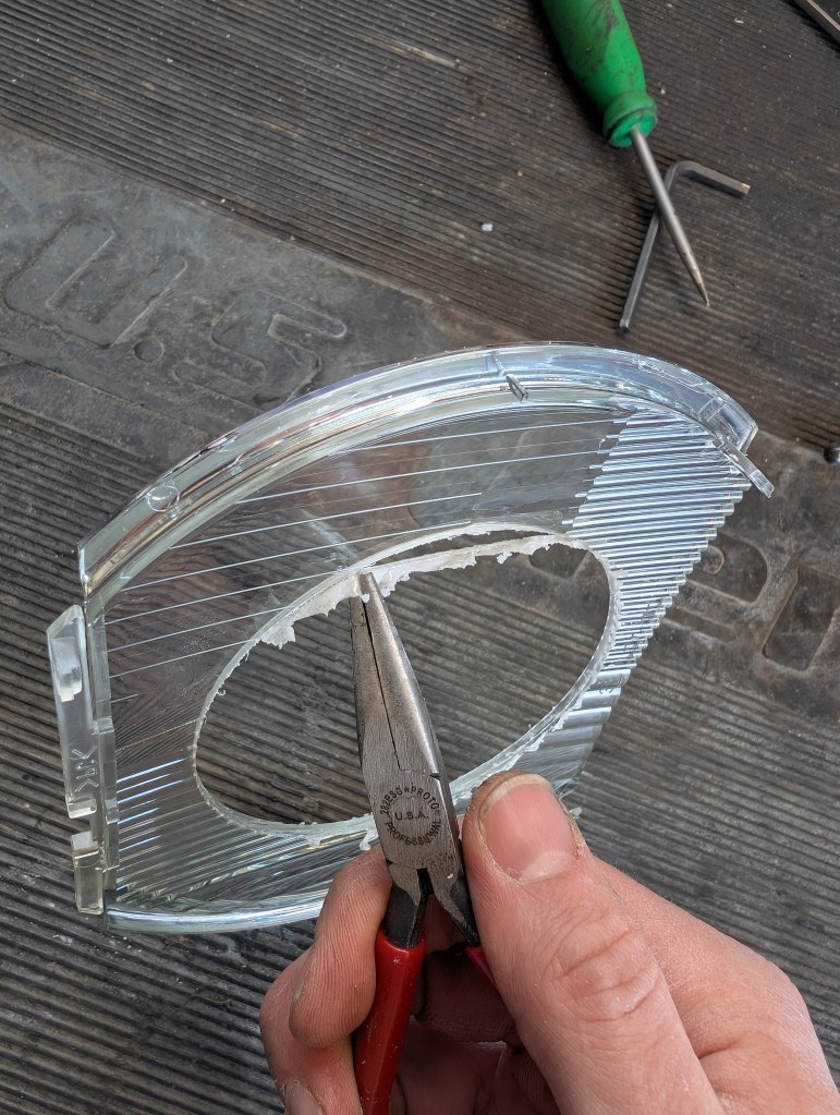
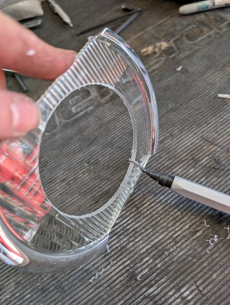
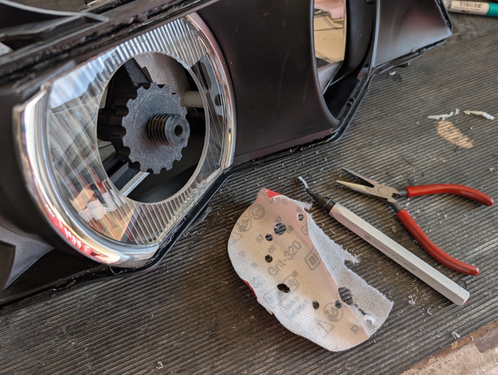
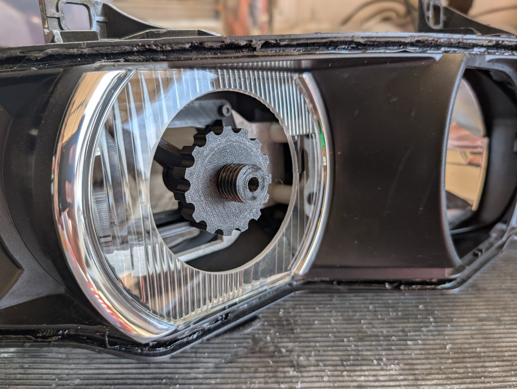
- After cutting the large hole, remove the outboard lens and clean up the edges as required. Remove the melty globes with a set of pliers by wiggling back and forth perpendicular to the cut, again being careful of the chrome surfaces and then deburred the corners once all the globs were removed on both the front and back edge. I also lightly sand the ID of the hole to clean it up with 320 grit sanding paper.
- Remove and discard the drill guide. Retain the 4mm SHCSs for BiLED final installation.
- Heat and separate the middle & rear housing if installing a DBG inner shroud.
Headlight final assembly
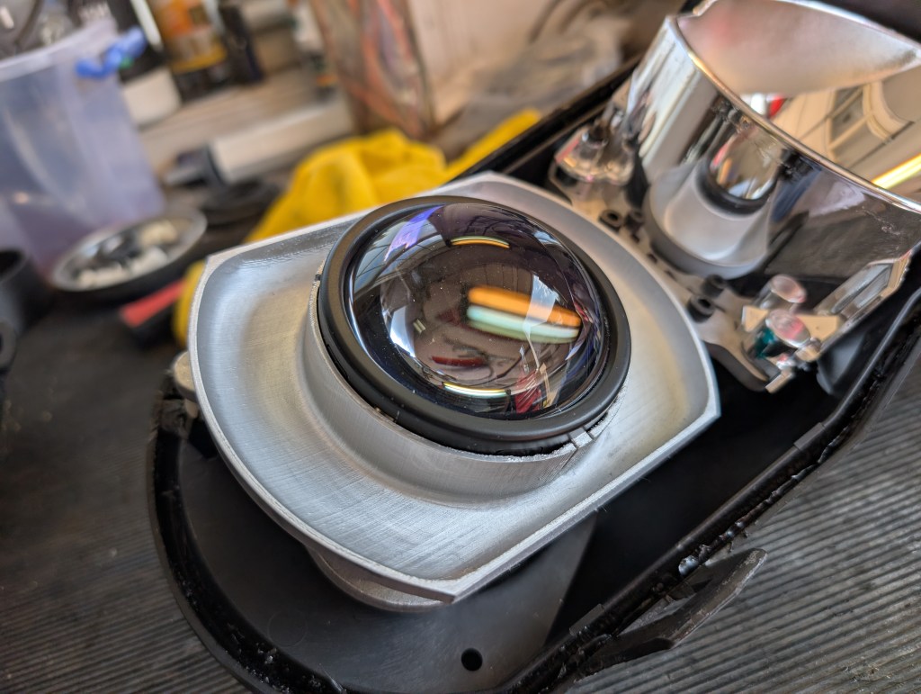
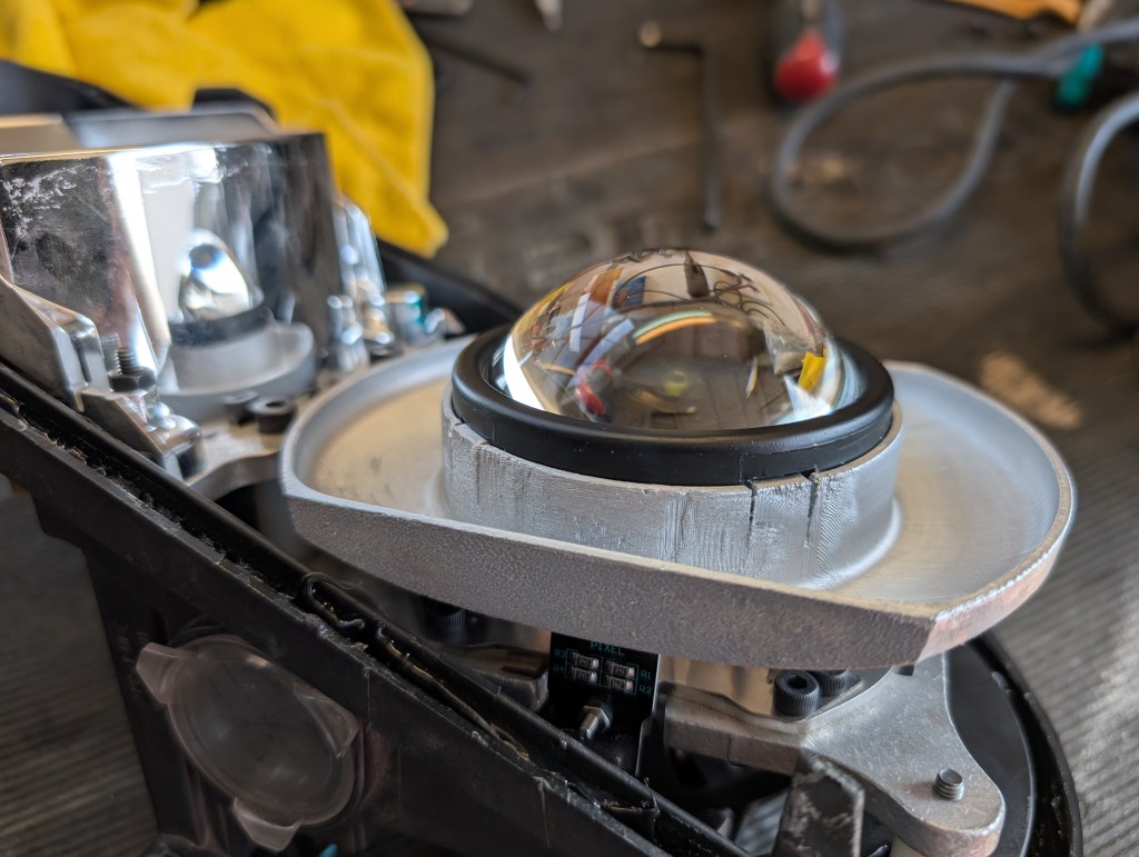
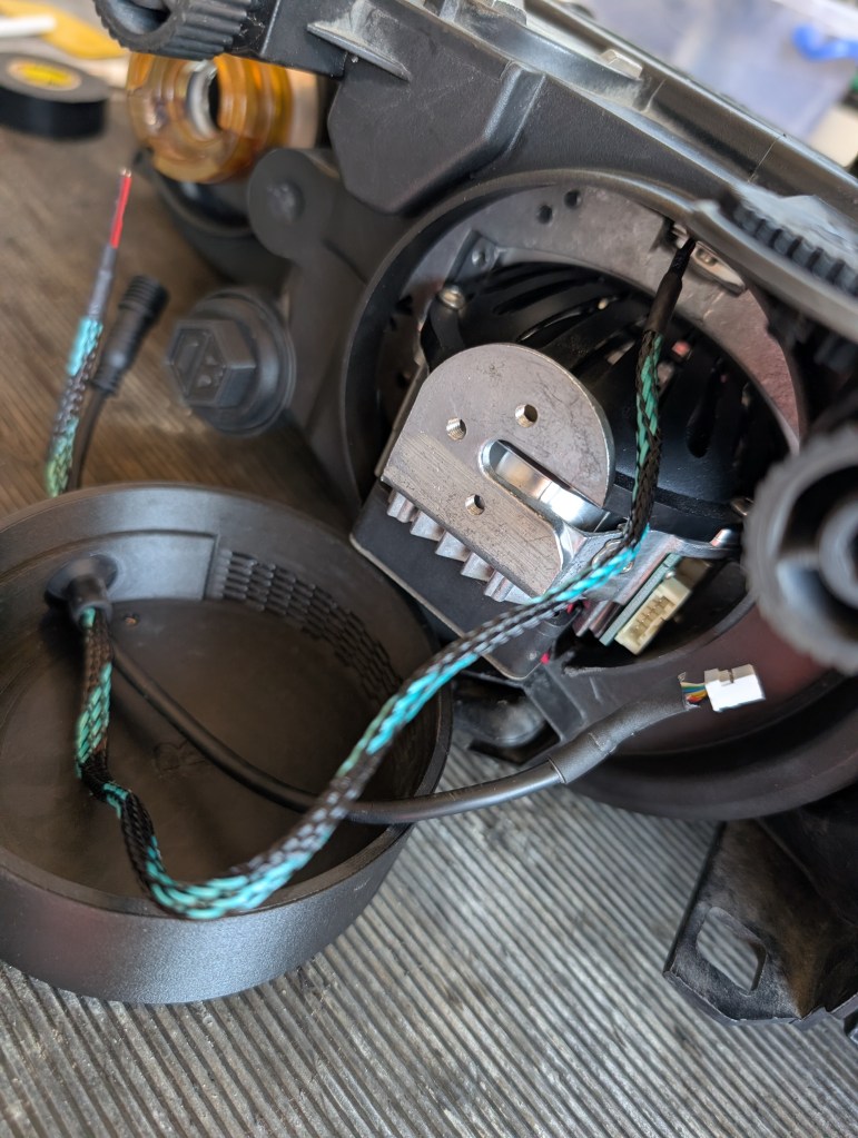
- Mount the BiLED onto the bracket assembly with the four each 4mm SHCSs. (disregard the extra SHCSs in my photo and the black/teal wire which is a “demon eye” LED which is outside the scope of this DIY). Now is the time to remove the protective film on the lens that I took off during prototyping.
- If used, mount the DBG inner shroud onto the BiLED ensuring the three mounting clips are aligned to the holes in the BiLED body. There is some clearances in the mounting clips to allow adjustment of the upper/lower edges of the shroud with the rear housing edges for best alignment.

- Reattach the middle and rear housings using a heating method that is a lot like disassembly with a cycle of general heating of the full perimeter of each housing and then focused heating for any spots that are stubborn to get them fully seated and clipped together.
- If removed, remount the turn signal. To reduce risk of stripping the screws during install, first turn them counter clockwise to “feel” when the screw seats into their original hole cut into the plastic turn signal. After seating install as expected ensuring the o-ring is also in place.
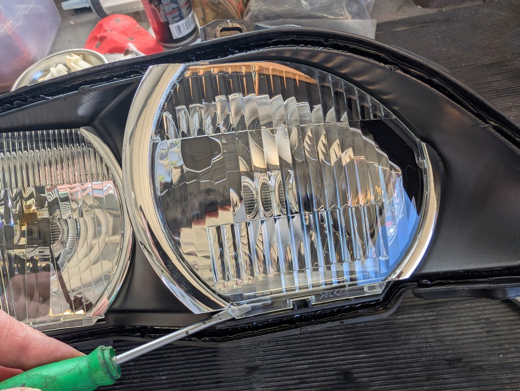
- Reinstall the chrome ring inner lenses ensuring that both hooks are engaged at the upper half and that the lower edge tab/notch are aligned.
- Now is the last chance to remove any finger smudges on the inner lenses, BiLED or turn signal.
- Reattach the outer lens to the middle housing with the same heating method. Ensure the three pieces are fully seated together and reinstall the 7 spring clips in their respective locations. Take extra time here to ensure the inside of the lens is clean and free of fingerprints and debris.
- Reinstall the breathers in their respective locations and the high beam weather seal.
- To install the DBG weather cover (They are marked with “L” and “R” for their respective side on the inner surface of the cover):
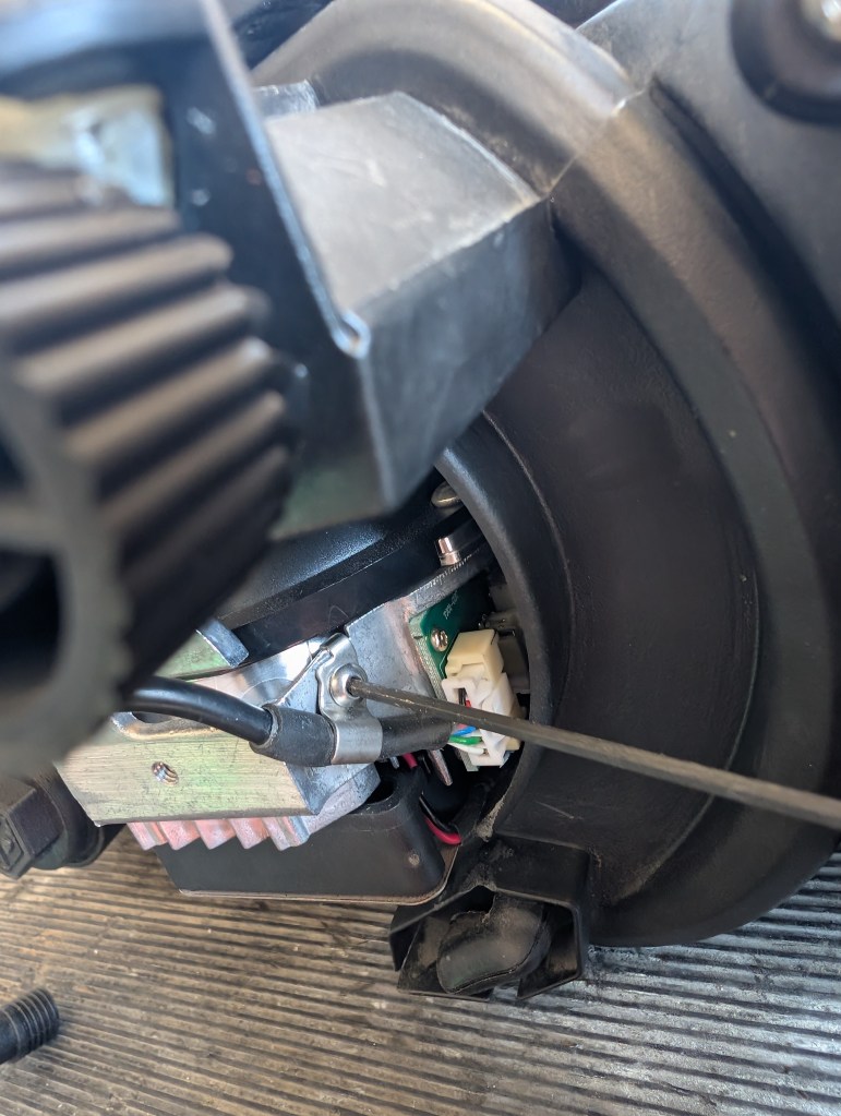
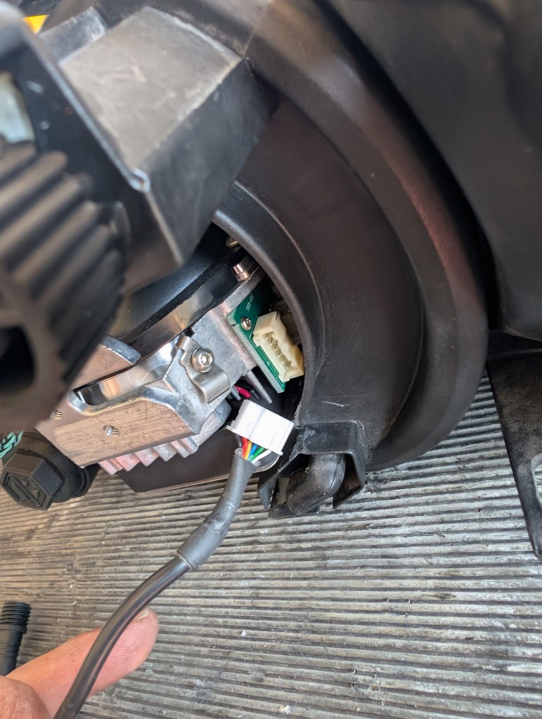
- Dismount the BiLED wire harness from the unit by removing the wire retainer and unplugging the white connector.
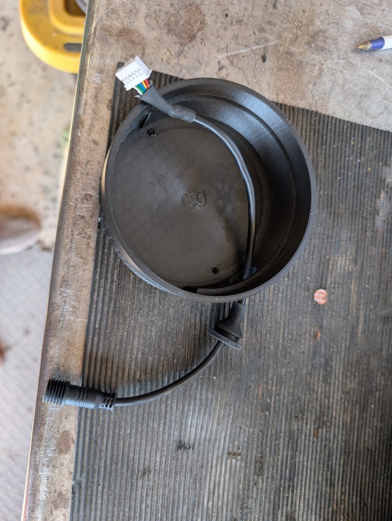
- Feed the harness through the DBG weather cover and seat the grommet. Pull the harness mostly to the “inside” of the cover and reattach the wire retainer and connector.
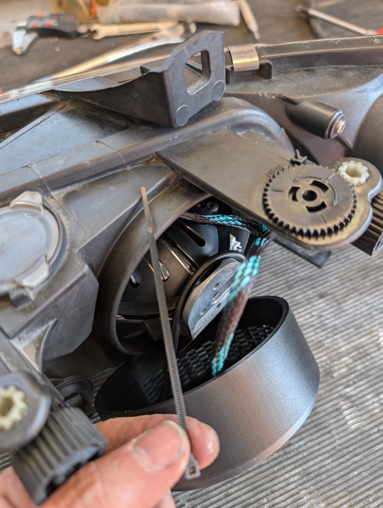
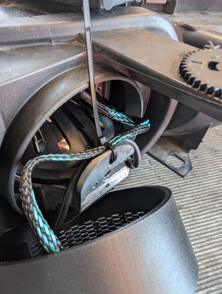
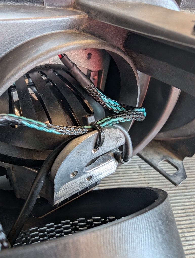
- To ensure no interference with the weather cover, route the wire harness over the BiLED housing and zip tie to FWD face of the flange at the rear of the BiLED utilizing the upper hole.
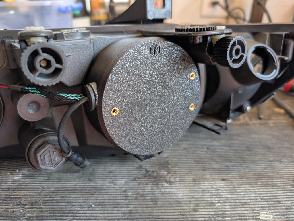
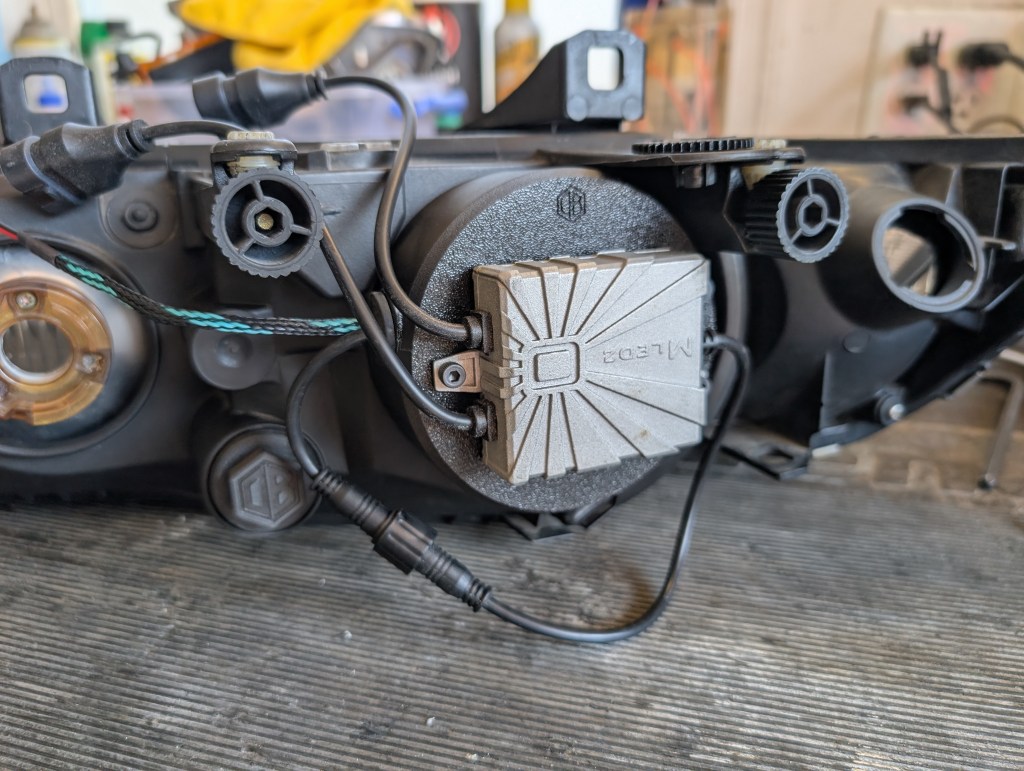
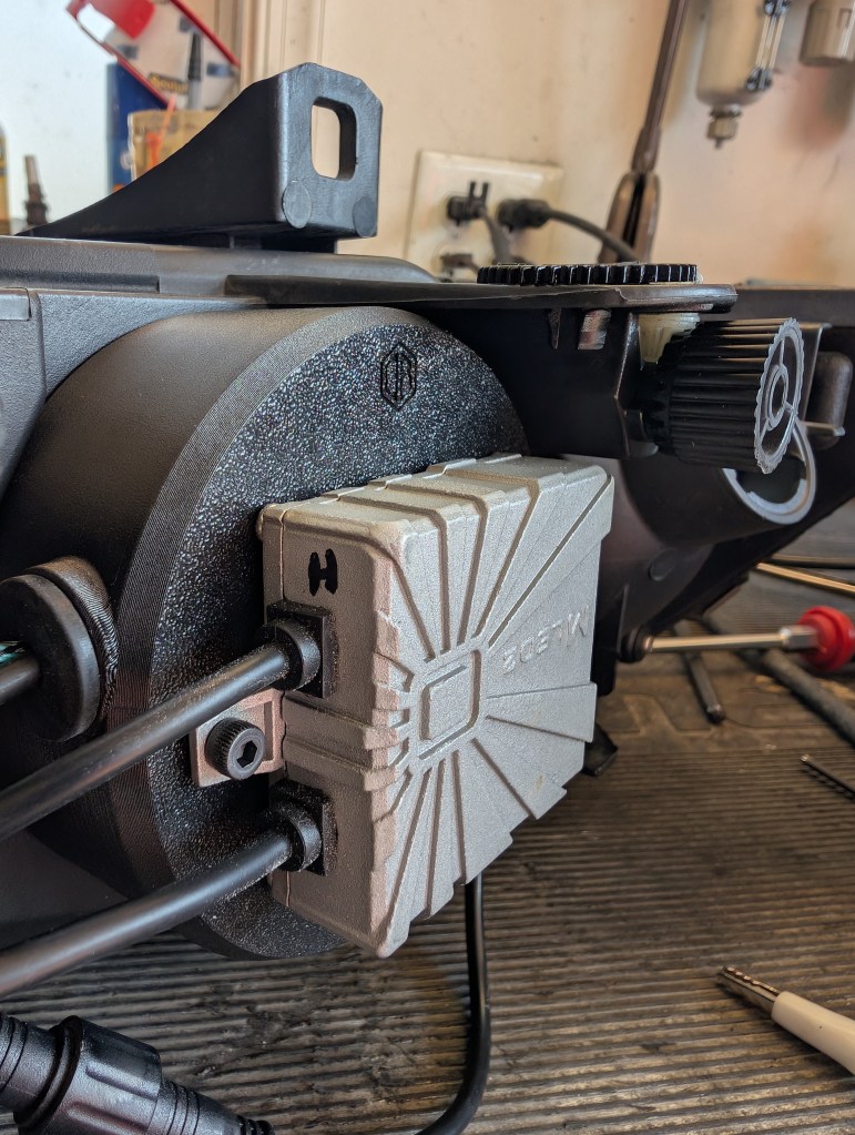
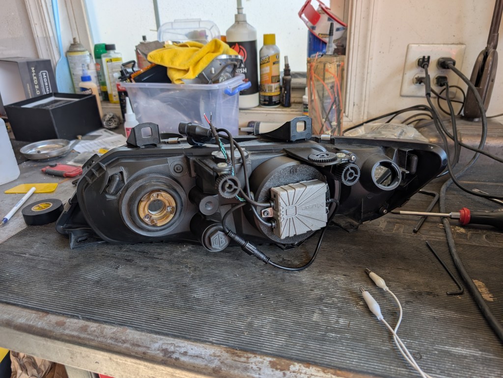
- The weather cover can now be pressed onto the rear housing the “DB” on the back of the housing should be at the 12 o’clock position.
- Mount the LED driver to the weather cover using three each 4mm SHCSs and connect the driver to the BiLED plug.
- I added an “H” to my driver to reminder myself which was the Highbeam lead
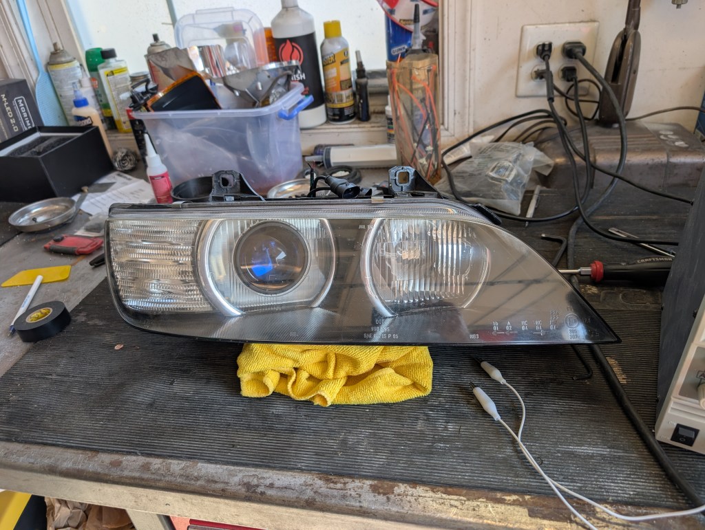
Outer lens refreshing:
I like to doll up my lenses (not photoed) and have had good success with the Cerakote system so far. For deeply pitted/scratched lenses a more aggressive approach may be needed and is outside the scope of this DIY but there are plenty of headlight restoration DIYs out on the internet.
Congratulations you completed one side… now you get to do it all over again.

Leave a comment