NOTE: I will be updating with photos and such when I get through my seat repairs but due to many kits being shipped and my limited time I wanted to post the Installation process steps at a minimum. I will be making formatting edits when I can get to a computer. Please email me with any questions or feedback.
The Double Bee Garage seat angle kit requires installation beneath the carpet due to the sizing of the base’s footprint to maximize strength and reduce metal fatigue at the chassis interface. To gain access to the seam between the two carpet pieces the seat(s) must be removed from the car.
If you need to order a seat riser kit or want more specifics on the kits, it can be found HERE
Tooling:
13mm socket
16mm socket
16mm box wrench
5mm Allen key/socket
Misc extensions
Torque wrench (23, 40, 43, 48Nm)
Trim removal tool(s)
Small/medium pry bar
Soft bristled brush
Cleaner of choice
To remove the seat and minimize risks of damaging the interior parts to the car this is the process I use.
The seat is held to the floor of the chassis by a pair of 13mm nuts at the front and a pair of 16mm bolts at the back. There are four electrical connectors beneath the seat that need to be disconnected. The lower seatbelt mount is required to be disconnected from the seat base.
NOTE: Prior to disassembling the angle kit as arrived, note the orientation of the washers for reassembly during installation.
- With the seat in the aft most position, loosen the two front 13mm nuts. The nuts must be close to fully installed for clearance during seat movement at this time.
- Position the seat to a fully raised and forward (FWD) position to gain access to the rear bolts and remove the 16mm seat bolts. Also remove the 16mm bolt for the seat belt lower mount.
- Position the seat fully lowered and aft position to remove the front nuts.
- With all the fasteners removed, position the seat with the sliders centered over one another and ensure it is fully lowered with the seat back fully erected.
NOTE: Ensure the seat height is fully lowered and sliders equal at this point to maximize space during removal. - lift the seat off the forward studs and shift it forward in the cabin space to allow it to be tilted backwards to gain access to the two large gauge power connections (motors and seat heater) that are connected on the outboard side of their respective seat about centered on the seat bottom. They each have two clips (top and bottom) that are compressed and removed in the aft direction to disconnect from the seat.
- The other two connections are at the aft edge of the seat bottom near the middle and will be a small black plug for the seatbelt circuit and a yellow plug for the SRS system. Tilt the seat FWD and disconnect the two small connectors.
CAUTION: With the yellow SRS plug disconnected do not turn on the key ignition or you risk triggering a SRS fault/dash light that will be required to be reset with special tooling.
With the five fasteners and four connections removed the seat is ready to be removed from the cabin. - To reduce risk to scratching the interior door trim I remove it by prying with a trim tool to release the three plastic pressure clips (fwd, middle, aft) and placing it out of the way. This trim will be required to be removed to lift the carpet seams anyway.
NOTE: Seats are heavy, awkward, and can easily damage interior parts. A second set of hands/eyes is highly encouraged but not required.
- For a driver seat removal without removing the steering wheel as interference, I lift the seat up and angle the seat back towards the passenger side of the cabin over the center console enough to clear the sliders above the door jamb. When the sliders clear the jamb the seat is rotated into a horizontal position and fully removed from the cabin and set aside.
For a passenger seat removal I lift and tilt the seat back out of the door opening. Care is needed to ensure the slider parts don’t contact the center console as the seat is rotated up and into a horizontal position to remove out of the cabin. - With the seat out of the way and the interior door jamb trim removed the seam of the carpet is able to be lifted/separated and the FWD section is lifted to allow access to the floor studs.
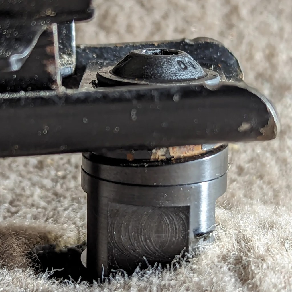
CAUTION: If previous using the coupling nut angle kit it is highly suggested to inspect for any damage to the support structure about the stud for cracking/tearing prior to Installation of the DBG angle kit. I am aware of three cases there was structural damage from the use of these prior kits. - Ensure the surface of the chassis and the stud are free of debris (vacuum/clean with brush and cleaner as required) and install the pair of angle kit bases using an 18mm wrench. The bases should be installed and torqued to 22Nm.
- Rearrange the carpet back into its original position.
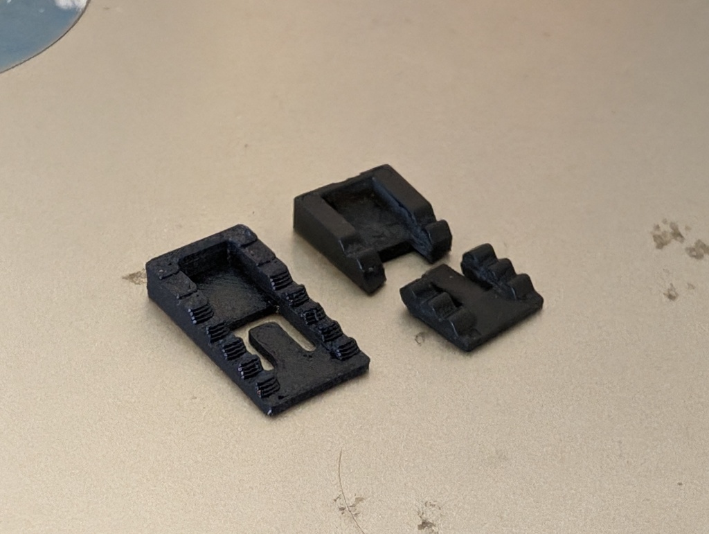
- The two circular taper washers should be installed onto the base. Ensure that the washer is installed with the face perpendicular to the hole is face DOWN against the base. The larger taper edge should be position FWD on the base, this will be fine adjusted later during reassemble so only rough positioning is needed at this point. The outer diameter of the round washer should be parallel to the outer diameter of the seat base and then washer and base mating surfaces should be in full contact.
- With the base protruding through the carpet and the round washer installed, the seat is returned into position within the cabin in reverse order of removal.
CAUTION: Ensure the wiring harness is positioned not to interfere with landing the sliders on the floor.
- Prior to making any fastener connections ensure the 4 electrical connectors are remade and securely clipped in. Following the electrical connections the seat should be maneuvered to land the two FWD slider holes on the angle kit bases atop the round taper washer.
- With the slider on the DBG bases install the square taper washers onto each base within the slider frame. The square washer should have the larger tapered edge in the AFT position and the Visibly milled face UP. Loosely install the two bolts using a 5mm Allen key.
CAUTION: Do NOT tighten fully the FWD bolts at this time to allow slider movement for rear bolt alignment/installation. At the same time they must be nearly fully installed to not interfere with the upper slider movement required to access the rear bolt holes. - To gain access to the rear bolts reposition the seat in its FWD and Raised most position. Reinstall the rear bolts and torque to 43Nm. With the rear bolts torques reposition the seat fully AFT.
- Visually inspect the round washer position with the seat slider. The tapered face of the washer should be making near full contact with the slider when properly positioned.
- If the washer is needing to be rotated into position loosen the FWD bolts a few turns to allow a few mm of clearance. Using a smedium pry bar (or otherwise) lift the slider off the washer to release the pressure on the washer which will allow it to be rotated by hand and reposition the round washer. Remove the pry bar and recheck the contact. Repeat as necessary to ensure fully contact for both inboard and outboard slider. With the round taper washers correctly positioned torque the FWD bolts to 40Nm.
- Reconnect the seat belt to 48Nm (Literature also requires thread locking compound on this bolt) to finish the installation.
- Position the seat to your preference and enjoy.

Leave a comment