When I installed the Eurosport Twinscrew, I had plans to get into the details of the old Romraider and self tuning aspect of it eventually. I was inspired by a buddy’s desktop setup to able to connect, read, and write to the DME in the comfort of an office or on the couch.
With a quick trip to the local U-pull-it, I grabbed a spare MS41.1 DME, the DME connector, the 20-pin diagnostic connector and the OBD2 port.
Any mid/late-ish 90’s 328/528 with a M52B28 should have the required bits. Take as much extra wiring lead as you can from the donor to ease assembly with the least amount of joints later.
The 20-pin really isn’t necessary for an MS41 bench top rig for the sole purpose of reading/writing to it but I over do everything and who knows what I might get into in the future.
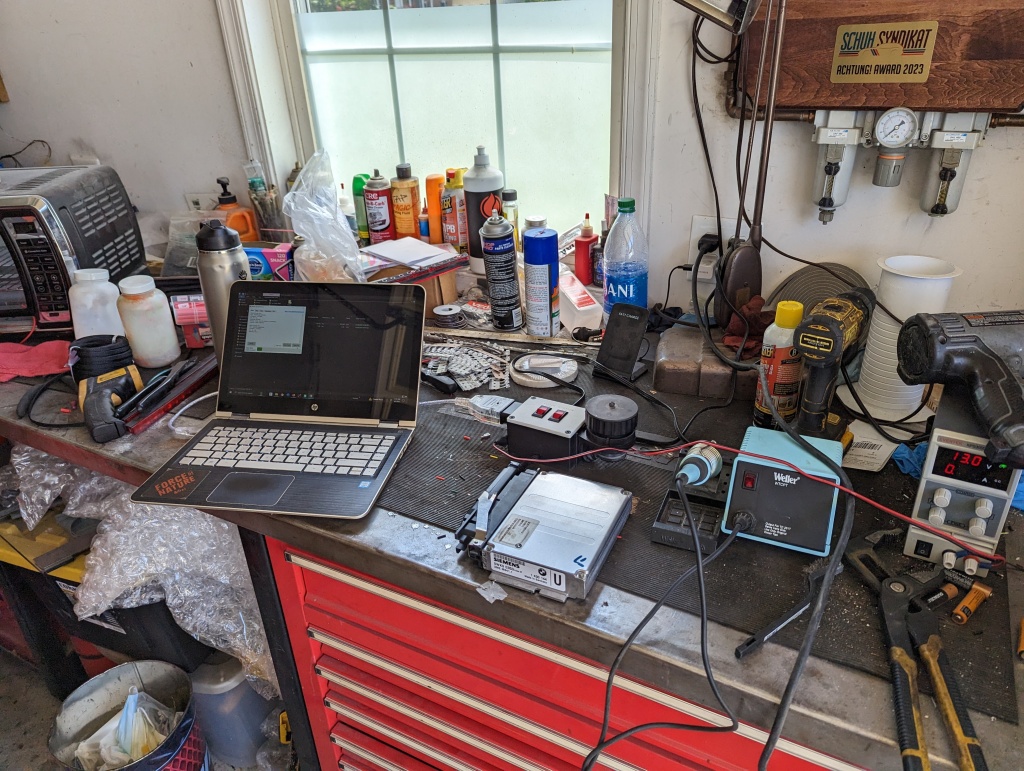
Here is the final results:

OEM Parts list:
MS41 DME
DME connector
OBD2 port
20pin diagnostic underhood port (optional)
Materials list:
Rocker switches 2 ea
Female spade connectors 6ea
Ring terminals 2ea
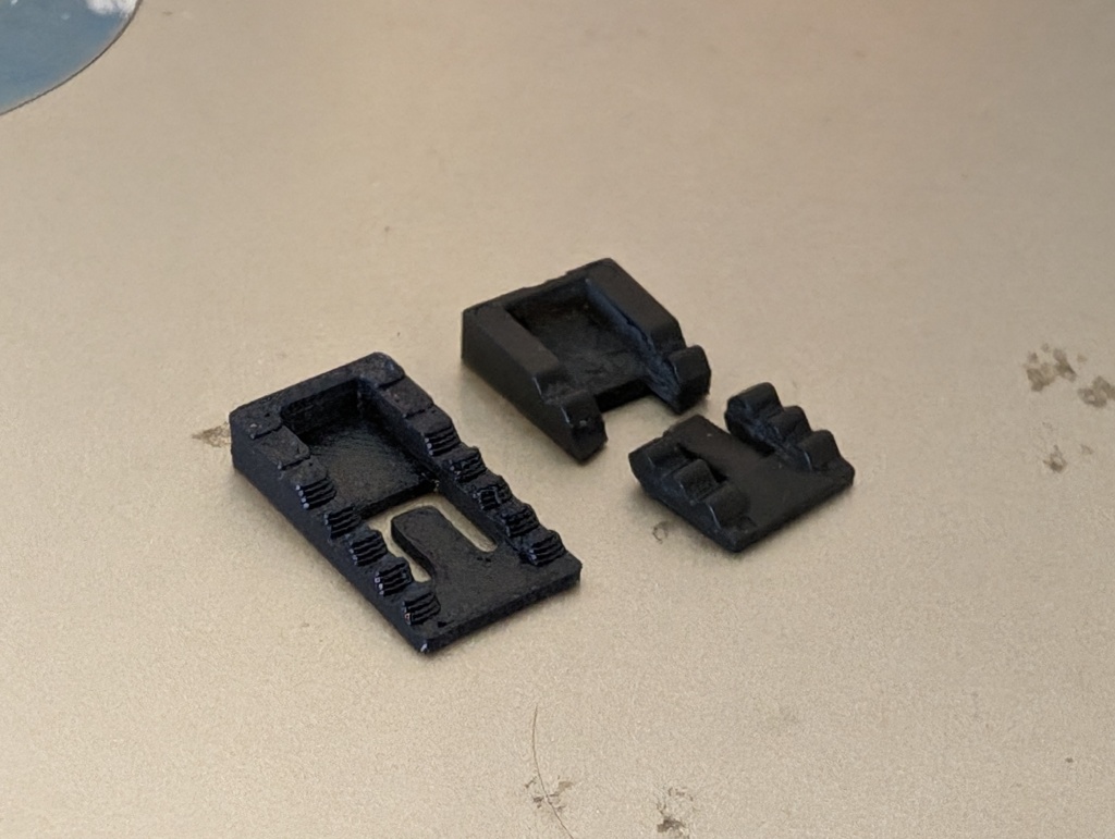
Project box (Free downloadable 3D print file)
Wiring
Fuse holder
5A fuse
Solder
Solder Flux (optional)
M6 flange nuts 2ea
M6 bolts 2ea
Screws 4ea (#6x 1” CT drywall screw)
Electrical tape
Heat shrink (optional) 1/8, 1/4, 3/8
Wire loom
Tooling:
Soldering iron
Phillips Screwdriver
In-line wire stripper
Standard crimp pliers
Electrical plug de-pinning kit (optional)
DC power supply (optional)
My box is wired as shown in the schematic below.

The box uses an external power supply to operate. To ensure there are no issues with reading and writing the DME a dependable power source is highly recommended.
I added a bit of complication to the wiring by using lighted switches when toggled on, but they aren’t required.
The printed box has provisions to press the M6 nut into the outer wall and the bolt threads in from the inside of the box (I used flanged nuts but that is because that is what I had), you’ll attach your power and ground eyelets with these bolts. The bolts should be long enough to extend through the installed nuts and I use a set of alligator clips from my power supply.


The switches linked should snap directly into the lid. The gold spade is the ground for the light function. You’ll need to ensure the constant power is on the correct spade to operate the light when the switch is toggled to the on position. If the light is on when toggled in the off position, switch the power leads and the switch installation orientation.


My OBD2 plug was a bit damaged so I had to modify the box to fit it, unfortunately if using my box you’ll need to remove the screw mounts on it but when assembled the box secures the plug no problem.

The 20pin should click into place using the original clip that mounts in the car.

I, being extra of course, de-pinned all the uneeded pins that were in the 20-pin and DME connector; however, this could be accomplished just the same by clipping them flush with the edge of the connection without much concern of shorting or having issues.
I also added the extra loom on the DME wiring that was exposed outside the box as well for added protection.

As far as software goes I used the website OpenMS41 as a resource and bought their MS41 Quickflash software. I have successfully used it to read and write DMEs. I have yet to learn how to use the Romraider parts/definitions to modify the coding, but have had others help me that helped develop the MS41 Quickflash program to flash the files using this benchtop rig.

Leave a comment