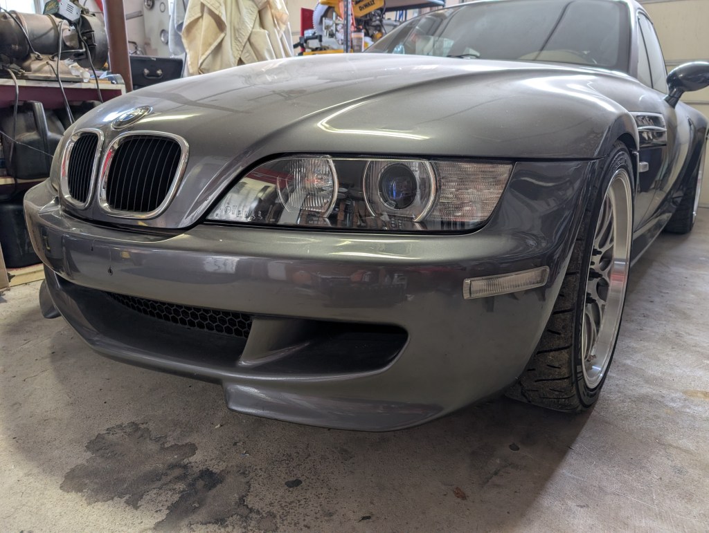
If you’re still catching up to what I’ve done to my Coupe I’ve installed one of the infamous Eurosport twinscrew (ESTS) superchargers. All the old forum threads, when ESTS chargers were in their heyday, rant about the torque monsters they are and with the removal of the ACS throttle body I wanted to have some sort of traction control system still available in the car. The train had already long since left the station for any hope of a Racelogic system that was the “bee’s” knees when available so that left me in a bit of a pickle.
Enter RaceTCS, the “new Racelogic” out of Poland. Googling about got me a whole bunch of Corvette and Mustang forum posts and Youtube videos of people raving about it. The updated electronics and proven application of “if the domestic guys can get it to work” had me drink the koolaid and decide to try it out even though a random company from Europe kind of had me sketched out. A purchase was made for the RaceTCS V2 package and the waiting game began. The system works by tapping into the oem wheel speed sensor signals and intercepting injector firing pulses to reduce power on the millisecond level. This provides smooth and predictable intervention and can be dialed up or down via the turn of the provided knob.

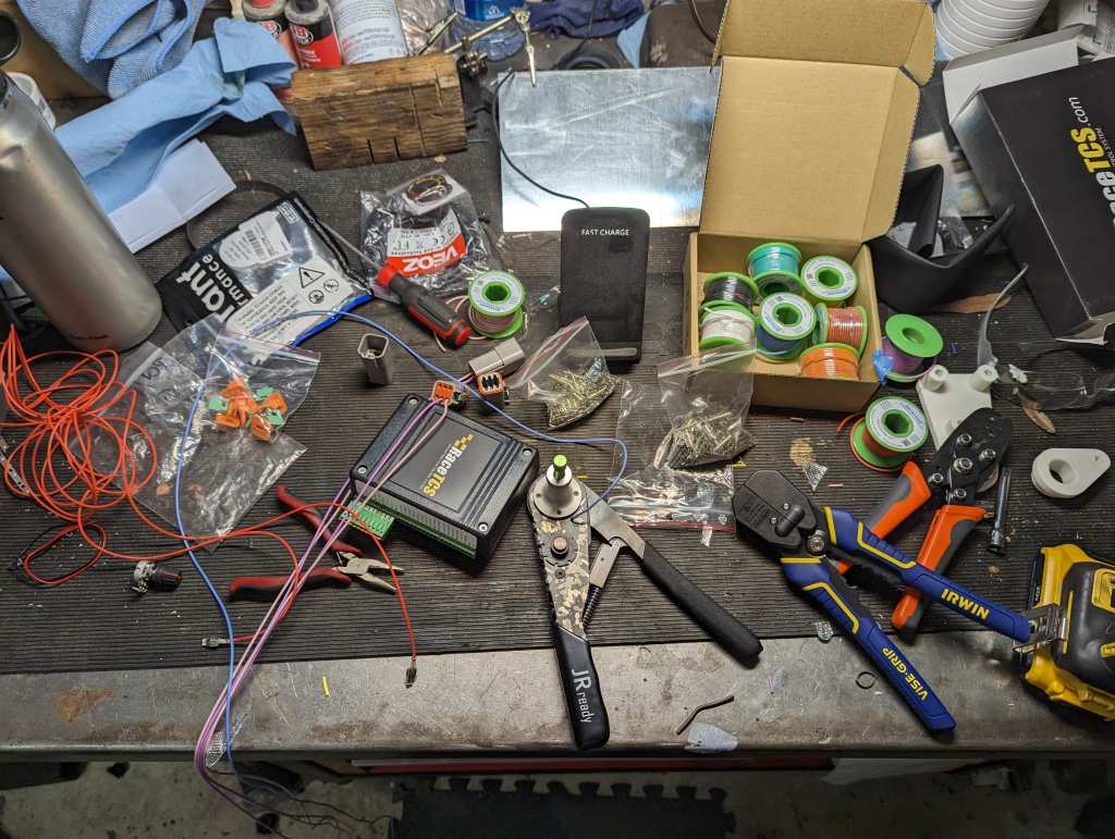
Surprisingly, just a few days after purchase the box showed up without a hiccup. It was well packaged and exactly as described. The box included the logic box, connectors, potentiometer (for selecting the level of nanny desired), a led, and a few resistors that may be used in certain applications.
Wiring was up to the user to source and fabricate the harness, which is a good and bad thing. Choice paralysis of wiring is a real thing, amazon (et. all) has oogles and oogles of options so just getting to the add to cart and buy it was taxing. The installation instructions are provided via pdf download and required two suggested wire sizes dependent on their service. After getting the wiring in hand the push-to-connect connectors were new to me and had a bit of a learning curve but simple to use once understood, but more on that later.
My looming deadline to get the car back together for schuh sydikat 2023 and the list of projects to get the car drivable was daunting, I was trying to get the traction control buttoned up and i was having MAF/fueling issues I was troubleshooting to get the car to run right. As the racetcs intercepts the injector signal wiring to control grip, I was attempting to not add more variables to my maf troubleshooting. Long story short I ended up getting the system in place but never read the last page or so of instructions in the manual that indicate installers need to initialize and calibrate the system (which doesn’t look hard) but I still have yet to accomplish through a series of unfortunate events. I made it to Schuh, and drove the snot out of the new ESTS powered Coupe apparently without traction control and not ever needing it. That being said, I will be initializing, calibrating and using the system when the car is running again.
Materials required:
RaceTCS v2
Deutsch connectors (multipack) (6pin only pack)
20 awg wire
16 awg wire
7.5a (a 5A would likely suffice as well) fuse and holder
Ring terminals
Solder
Electrical tape
Wire loom
Heat shrink (optional) 1/8, 1/4, 3/8
Tools:
Deutsch solid contact crimp pliers
Drill
Wire fishing strip
Straight pick or small flat head screwdriver
Small Philips head screwdriver
Electrial plug de-pinning kit (optional)
The following is provided for informational purposes only. Following these instructions are at your own risk.
Being that this system monitors wheel speed sensor signal pulses and intercepts fuel injector firing signals, i wanted to ensure the highest quality connections could be made. All of these joints are either hard soldered or solid contact crimped where needed. Use of t-taps and crimpbutt connectors is not recommended.
First things first, i wanted to pre-build the harness to limit my time bending, twisting, flipping etc. Etc. Etc. In the car. That being said the wiring loom i made is excessively long but later cut to suit in the car which made for some material waste. There are three connectors for the racetcs box, they are all easily marked and well defined in the provided pdf from racetcs. I premade the injector interrupt wiring with 6-pin deutsch connector such that if the system were to act up i could just open the dme box, unplug the racetcs connects and plug my oe wiring back together.
The deutsch connectors come with all the parts needed to assemble them and the jrready does the real important work of ensuring the crimps from the wiring to the pin is solid. I picked 6 colors of the 20AWG wire to identify the individual injectors, cut to length, twisted the first few inches by hand and taped them together. After grouping i placed one end in my vice and the other was chucked into my drill and give it a good whirl. While not as fancy as all these loom builders on instagram, it gets the job done, makes for tidy tight wiring and is flexible. After twisting with the drill the loom is taped every few inches with electrical tape
 .
.
After twisting, I took each free end and put one male and one female connector on. Loading the respective pins into the crimper, setting the proper depth on the tool for the pin to ensure the teeth compress the stripped back wire in the pin barrel, and installing in their respective plug is super simple. I preinstalled the expanding loom for a couple feet before installing the pins into their plugs, optionally the use of some split loom over the wiring later works too, for the short jaunt it takes from the DME box into the firewall.

As seen above I ran the harness into the DME box and at the time just connected the plugs to themselves to keep them clean. I fed the loom through the inboard rubber boot to exit the DME box and fed it into the rubber grommet I had previously used to pass my external oil temp and water temp sensors through. For the factory set up guys and gals, this grommet is just below the Secondary Air Pump (SAP); however, my SAP has long since been removed so the photo may be a little misleading due to the power terminal location pictured since I am non-standard.


The interior location of that firewall grommet is just below the top edge of the carpet in the passenger side footwell (for us LHD folk) just inboard of the wiper control module (grey box with the blue top). When fishing any wiring in the car my trick is to go to your favorite home material box store and find the largest zipties they sell, snip the end off, and use a good bit of electrical tape to secure the ends of the wiring to the ziptie tail to feed it through the penetrations. In particularly tight spots I have been known to wipe down with a healthy dose of isopropyl alcohol to add some lubrication.
Once inside the cabin, I identified which set of wires went to which plug in the DME box with a multimeter continuity check and identified the InjIn and InjOut plugs in the DME. It really makes no difference which is which as long as you identify them correctly. I marked the DME side plugs with an arrow away from the DME for InjIn and an arrow toward the Injectors for InjOut.
Now begins the slightly terrifying part, cutting injector wiring and piggy backing into ABS signal wires. While the actual work is not hard, the ramifications of error could be significant. I took my time and triple checked pin numbers and casing colors before I did any physical work. I segregated them one at a time for each connection and made notes as I went to ensure I could troubleshoot my work in the event of any issues. (a link to Wiring schematics for other chassis is provided in the “useful links” page on the navigation bar)
For my 2000 Mcoupe (S52) the fuel injector wiring in the DME harness is as follows:
#1: .75 BR[brown]/WS[white], PIN6
#2: .75 BR[brown]/RT[red], PIN 5
#3: .75 BR[brown]/GE[yellow], PIN 22
#4: .75 BR[brown]/BL[blue], PIN 24
#5: .75 BR[brown]/GN[green], PIN 33
#6: .75 BR[brown]/VI[violet], PIN 23
The .75 is the size of the wire.
To gain access to these wires pin identifiers I needed to disassemble the DME connector a bit, while not wholly required, I felt it necessary to confirm reference material color identification and pin identifiers matched my harness. I disconnect it from the DME using the lever lock bar. Next, I remove the clamp/ziptie/et all device that is holding the small cover to the main body next to all the wires exiting the connector and remove the small cover. Finally I remove the Philips head screw to allow the larger lower cover to be separated from the connector itself which will gives plenty of access and allow verification of pin # identifiers. This is the same process of the ABS/ASC connector we will get to inside the cabin in a bit. Once the wires are properly identified, I cut each wire a few inches outside of the DME connector cover to allow installation of pins and the respective Deutsch connector to match my new loom to each side of the wire. After making up all my pins and plugs, I reassembled the connector covers and installed a ziptie to hold the small cover in place. I found the use of flush cut snips to be a game changer when using zipties as they leave the stubs of the ziptie flush with the locking device and don’t create little razor blades to snag my fingers on later.

Moving inside the passenger footwell I identified my ABS/ASC module which looks very similar to the DME to pick up the wheel speed sensors. I disassemble the ABS connector in the same process I did the DME connector to verify color coding and pin identification against the reference wiring diagram.
For my 2000 Mcoupe (S52) the wheel speed sensor wiring in the ABS harness is as follows:
Left front: .5 GE[yellow], PIN 36
Right front: .5 GE[yellow], PIN 15
Left rear: .5 WS[white], PIN 13
Right rear: .5 GN[green], PIN 11
Once I identified the respective wires, I used my inline wire strippers to strip back the wire casing to allow to tap the wire. I use a Weller WTCPT soldering iron but any iron will work. To make a strong electrical and mechanical joint to ensure longevity of the connection I make my T-connection joints by performing the following:
1) Inline strip original wire
2) Using a straight pick or small flathead screwdriver separate make a “hole” in the original wiring to pass the new wire through
3) (Optional) Apply flux to the new wired stripped end
4) Insert the new wire end through the hole created in step 2 and wrap the new wire around the existing exposed wire to form a strong mechanical and electrical joint
5) Apply solder
6) Protect new joint with electrical tape* or heat shrink
*Note: I am a firm believer in 3M Super 33+ tape when I cannot heat shrink. For any long term usage of tape it is all I use.

Due to my installation schedule I took the shortcut path of use of electrical tape to isolate my new connections. Ideally and likely in the near future, I will be pulling this connector back apart to de-pin the wire and replace the tape with heat shrink. Granted this is likely overkill as the same 33+ tape I applied in the fuse box eight years ago roughly looked the exact same as the day I applied it when I looked at it when adding my fuses as discussed later.

The last few wires to install in the car are the 12V switched power [ACC power], wiring and installation of the potentiometer knob, DiodeOut [LED indicator], and grounds.
There are three grounds in the RaceTCS harness which are suggested to be the larger 16AWG wire vice the 20 AWG used for everything else. There are tons of access points in the dash to attach a ground. I’ve previously installed a Euro style glove box which allows me a few points to attach to the dash crash bar which is a very easy grounding location. I made up three short pigtails into an appropriately sized eyelet and used a standard crimp plier to make my ground contact. In typical fashion of “belt and suspenders” overkill of work I do, I also tinned the ends of the grounds in the eyelet after crimping with solder.

For my application, I did this as a result of removing the ACS-TB and ACS TB position sensor, which I’ll get into in another article [future article]. The short story of the results of the ACS removal is that my ABS works as expected, but the ACS computer is not happy and leaves the ACS light in the cluster illuminated at all times. Since the RaceTCS has an LED indicator for when it kicks in, I decided to disconnect the ACS computer lamp signal and use the cluster light for my RaceTCS indicator in lieu of the included LED they provide.
ACS cluster light wiring is in the ABS/ACS connector with the wheel speeds sensors as follows for my 2000 Mcoupe (S52): .5 BL[blue]/BR[brown], PIN 31
I cut the above wire and protected the wire going into the ABS/ACS connector and then connected the side headed to the cluster to the DiodeOut pin of the RaceTCS harness.
Next up is the potentiometer knob. I wanted this knob to be accessible from the driver seat but out of the way as it would only need adjustment after initial settings in adverse weather conditions. There are two blanks in US-spec based S52 Mcoupes on either side of the steering wheel column, the left side is used for fog light switches in other applications and the right for euro-spec headlight level selectors. I had already installed a modified fog light switch to operate a hidden homelink garage door opener so the right side, and conveniently enough the knob fits very well in the right side’s blank so that is where it went.
[Missing photo of control knob place holder]
The RaceTCS provide the two connections on the knob that need to be made up, again I installed the exposed wire through the hole in the potentiometer, bent it over and soldered both connections and applied heat shrink over each respectively. The knob fits through the hole of the blank which is convienient for installing and then I used my ziptie wire fisher to slide it behind the AC&R bits to get it back into the passenger footwell.
Finally, I get to the last wire needed to make up the RaceTCS harness, the 12V switched power supply. During the installation of the ESTS air-to-water heat exchanger pump wiring in the fuse box the ESTS instructions provide parts and details on how to add fuses to the empty slots in the OE box. I had noted that there were three empty fuse slots which is the exact number I needed for the RaceTCS and the two AEM gauges. It was at this point that I decided to use the OEM spades to install them in the fuse box, which is above and beyond the minimum requirement and will be discussed in detail in a future post adding the fuses to the OE box. Alternatively, tapping into any 12V switch power and running an inline fuse holder under the dash near the RaceTCS could be done and serves the same purpose.
But to quickly explain what I did for the purposes of this article I tapped into the ACC 12V wiring in the fuse panel previously for the ESTS IC pump relay seen below as the black/blue wire below tapping into the green wire (2.5 GN) in the removed fuse block that supplies fuses 22-27 with switched power. I later tapped the three new fuse leads for the two gauges and RaceTCS onto the black/blue relay wiring and installed the fuses in the remaining empty slots. The downstream fuse wiring was then ran into the cabin using the same fishing technique, across the cabin, and into the passenger footwell for final connections.


Onto the final stretch, I finally make up the push to connect plugs of the RaceTCS hardware to all the wiring now ran into the passenger footwell. To be completely honest, a few had already been made up on the bench to a) familiarize myself with the use of this style connector which was new to me, and b) to minimize work done bent into the footwell. These bench made connections were the three grounds, after rough fitting in the car to length, and the 4 wheel speed senor wires that had to be made on the other end to the wiring in the car regardless. The RaceTCS instructions advise against tinning the free ends being put into the plugs; unfortunately, for the wire I purchased with a high strand count to maximize flexibility which made routing them a breeze, it was a double edge sword in which the wire did not have enough rigidity to overcome the push-to-connect style plug. So I inevitably had to tin each wire and use a mirco e-torx driver (a small pick, punch, or screwdriver could likely do the same but the torx was on hand and provided a flatter tip to push with) to push each tinned wire into its respective slot. I verified each tinned wnd was fully inserted, checked continuity with my meter, and gave a slight pull to ensure it was fully locked in place before continuing.
First for the injector wires, I re-verified which 6-wire bundle went to which component in the DME box, identified which color wire was in which pin of the deutsch connector and used that same pin number to correspond to the injector number it was controlling, (i.e. the pink (or whatever color it was) wire was installed in the Male and Female Deutsch plug Pin 1 in the DME box was used to its respective InjIn1 and InjOut1 plug)
Next was the wheel speed sensors, which followed the same process. Re-verify each signal wiring in the car and install in its respective LF/RF/LR/RR port in the RaceTCS plug.
This process continued for each of the remaining wires. The PotIn has two ports for the control knob in the RaceTCS plug and their orientation is irrelevant.
The provided USB cable should be plugged in and ran such that it is accessbile when everything is put back together. I plan to run mine into the glovebox similiar to the ipod cable (who uses those still?) from the headunit. Obviosuly the 3harness connectors should be pluged in and I stuffed the box into the empty space as previously seen in photos above.
Lastly, at the time of installation, I did not intend to flex the RaceTCS capabilities for Launch Control but I did pre-wire the ClutchIn signal wire for future use (seen as the purple bundled wire below). I made this determination based on the fact that I have not yet reinforced my rear differential mounts with the Randy Forbes kit sitting on the shelf and my schedule was too short to worry with it.
20/20 hindsight notes of my installation at the time of writing this that will be updated as applicable:
- I really wish I had been more complete in the reading of the instructions to know if the system ever should have kicked in during Schuh, but with the brand new 255/295 Yoko AD09 tires and appropriate throttle/brake inputs it was apparently never needed thankfully.
- I have yet to have any serious encounters with the ESTS setup and a wet road condition, the weather for Schuh was beyond perfect and the only other trips I took before an unrelated oil leak and subsequent identification of my rear end beginning to fail has put the car out of commission for the foreseeable future so any future setup and testing is yet to be determined.
- A compromise in 20AWG wire strand count to flexibility/rigidity would have made the push to connect plugs much easier to work with. The 16AWG used for grounds did not require any tinning of the stripped ends and pushed in very easily and saved a lot of time.
- I suspect I may need to replace my ACS bulb with a correctly sized LED for better operation but until tested I do not really know. The incandescent style bulb may be sufficient.
- The reference installations of Racelogic systems did not require any resistor inline with the wheel speed signals. My reading is my wheel speed sensors are Hall style (vs VR style) which per the RaceTCS instructions, if the output voltage is >5V, the resistor is required. Since I haven’t initialized the system to see the outputs in the RaceTCS software I’m not sure if this is needed for my application but would be as easy as just wiring inline the resistors provided with the kit in the 4 wheel speed sensor wires.
UPDATES April 2024!
- I initialized the system and our cars require NO extra resistor to the ABS wiring to scale correctly.
- Our ABS rings are 48 tooth count, which you will need for setting up the system
- I still have some playing to do with settings to figure out how everything works but the log files tracking accordingly and I could see the thresholds change as the traction dial was adjusted in the dash.
- I could not get the TCS repurposed light to light up on my latest trial but have since reversed the polarity in the controller to see if it was just a “firing” issue or if I still need to get the rear end looser for the nannies to kick in.

Leave a comment